Материал: m012900e
112 • I/O modules
Counter modules 750-404/000-003
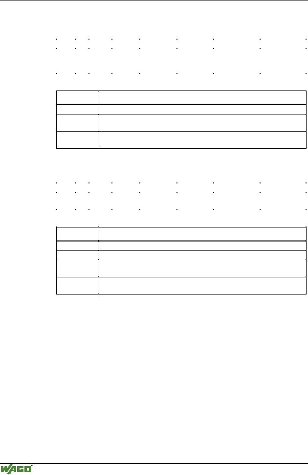
Structure of CONTROL and STATUS byte
The control byte has the following bits:
Bit |
7 |
Bit |
6 |
Bit |
5 |
Bit 4 |
Bit 3 |
Bit 2 |
Bit 1 |
Bit 0 |
0 |
|
0 |
|
0 |
|
TVD |
Output |
Output |
RANGE_SEL |
RANGE_SEL |
|
|
|
|
|
|
REQ |
value at |
value at |
REQ1 |
REQ0 |
|
|
|
|
|
|
|
output O2 |
output O1 |
|
|
Bit Description
TVD REQ
RANGE_SEL REQ1
RANGE_SEL REQ0
Request to change the maximum time without valid data.
Selection of the Integration time and the representation of measured frequency value.
Selection of the Integration time and the representation of measured frequency value.
The status byte has the following bits:
Bit |
7 |
Bit |
6 |
Bit 5 |
Bit 4 |
Bit 3 |
Bit 2 |
Bit 1 |
Bit 0 |
0 |
|
0 |
|
ST_ |
TVD |
State of the |
State of the |
RANGE_SEL |
RANGE_SEL |
|
|
|
|
GATE |
ACK |
output O2 |
output O1 |
ACK1 |
ACK0 |
Bit Description
ST_GATE
TVD ACK
RANGE_SEL ACK1
RANGE_SEL ACK0
State of GATE input (0=enabled, 1=disabled)
Acknowledgement TVD changed.
Acknowledgement of Range Selection, Frequency values are valid.
Acknowledgement of Range Selection, Frequency values are valid.
Modular I/O System
ETHERNET TCP/IP
I/O modules • 113
Counter modules 750-404/000-003
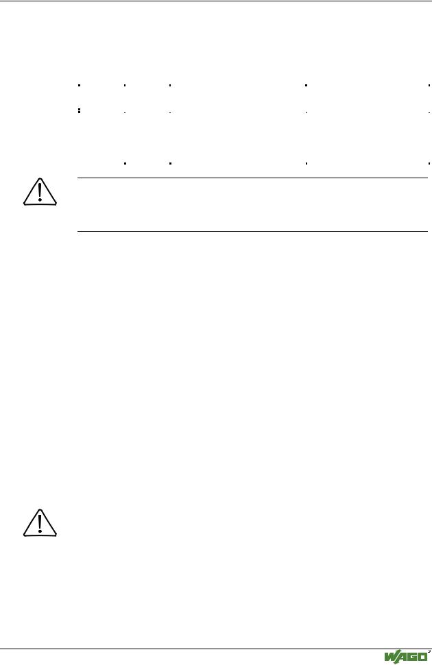
Structure of the Input and Output data
The input data represents the CLOCK frequency as a binary value. The representation depends on the RANGE_SEL bits in the CONTROL byte. Even the method of measuring is selected via these bits. The following table illustrates the different modes.
RANGE_S |
RANGE_S |
Method of measurement |
Representation of measuring value |
|
EL1 |
EL0 |
|
|
|
|
|
|
|
|
|
|
|
|
|
0 |
0 |
Integration over 1 Period |
Frequency in 1/1000 Hz |
|
0 |
1 |
Integration over 4 Periods |
Frequency in 1/100 Hz |
|
1 |
0 |
Integration over 16 Periods |
Frequency in 1/10 Hz |
|
1 |
1 |
Integration over 16 Periods |
Frequency in Hz |
|
|
|
|
|
|
Attention
When a new frequency range is requested, the application has to wait for valid data until the RANGE_SEL ACK bits contain the new frequency range. The maximum delay can be calculated using the following formula.
TDmax= 2 |
• |
Number of periods to be integrated |
|
actual frequency |
|||
|
|
If the gate is enabled the input data contains the last valid frequency value. In this state the application cannot request a new range.
The valid frequency range stretches from 0.1 Hz (100D) up to 10 kHz (100000D).
To recognize static CLOCK signals, a watchdog timer is implemented. The default value for the timer is 10s. The timer resets on every Power On.
The application is able to change the watchdog time during operation by using the CONTROL byte.
This can be initiated by writing the corresponding value into the output bytes OUTPUT_DATA 1 and OUTPUT_DATA 0 before setting the TVD REQ bit in the CONTROL byte.
The success of the parameter transfer is acknowledged by the module via the TVD ACK bit in the STATUS information.
Attention
The range of the watchdog timer stretches from 0 to 16383ms (0x0000H to 0x3FFFH) in steps of 1ms per digit.
Values which raise the permitted range of the watchdog timer are masked with 0x3FFF.
If the maximum possible frequency of the different ranges is raised (see the table with maximum frequency ratings), the module will return the non valid data 0xFFFFFFFFH.
Modular I/O System
ETHERNET TCP/IP
114 • I/O modules
Counter modules 750-404/000-004
4.2.1.1.7 Variation |
|
Up/Down Counter with switching outputs |
750-404/000-004 |
Technical description
The counter module also can be ordered as Counter with switching outputs with item number 750-404/000-004.
The counter module 750-404/000-004 begins processing with pulses at the CLOCK input. The changes from 0 V to 24 V are counted.
The counter counts up if the input U/D is set at 24 V. With an open circuit input or 0 V the counter counts backwards.
The terminals O1 and O2 work as binary outputs. Each output can be activated via specific bits in the CONTROL byte.
The high "on"states of the input and output channels are each indicated by a LED.
The counter module can operate with all WAGO-I/O-SYSTEM bus-couplers (except for the economy type).
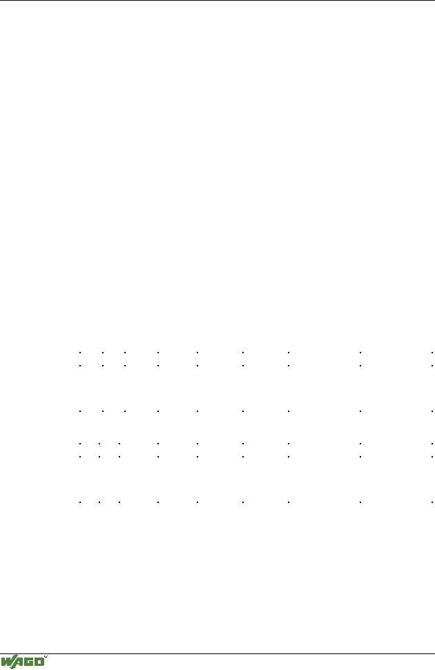
Organization of the input and output data:
The control byte has the following bits
Bit 7 |
it 6 |
Bit 5 |
Bit 4 |
Bit 3 |
Bit 2 |
Bit 1 |
Bit 0 |
0 |
x |
Set |
Block |
Output |
Output |
Output O2 acti- |
Output O1 acti- |
|
|
coun- |
counter |
value at |
value at |
vated depending |
vated depending |
|
|
ter |
|
output O2 |
output O1 |
of the counter |
of the counter |
|
|
|
|
|
|
value |
value |
The status byte has the following bits:
Bit |
7 |
Bit |
6 |
Bit 5 |
Bit 4 |
Bit 3 |
Bit 2 |
Bit 1 |
Bit 0 |
x |
|
x |
|
Counter |
Counter |
Actual |
Actual |
Positive signal at |
Actual signal at |
|
|
|
|
is set |
is blok- |
signal at |
signal at |
input U/D, |
input CLOCK |
|
|
|
|
|
ked |
output O2 |
output O1 |
counter counting |
|
|
|
|
|
|
|
|
|
up |
|
Modular I/O System
ETHERNET TCP/IP

I/O modules • 115
Counter modules 750-404/000-004
With the control and status byte the following tasks are possible:
Setting the counter:
Put Bit 5 into the control byte. The counter with the 32 bit value is loaded into output bytes 0-3. As long as the bits are set, the counter can stop and information is stored. The ensuing data of the counter will be conveyed to bit 5 of status byte.
Blocking the counter:
Bit 4 is set into the control byte, then the count process is suppressed. Bit 4 in the status byte communicates the suppression of the counter.
Setting the outputs:
Bits 2 and 3 set the additional two outputs of the counter module.
Switching the outputs dependent of the counter:
The bits 0 and 1 activate the function: output dependent setting of binary outputs. If the counter reading 0x80000000 is exceeded, output A1 is activated. For the output A2 only the bottom 16 bits of the counter reading are taken into account which means that output A2 is activated as soon as the counter reading 0x8000 is exceeded. Having reached 0 again, the outputs are reset. If bits 2 or 3 are also set, they have priority, so that the corresponding output is set independent of the counter reading.
The result of the counter is in binary.
Example how to activate the digital outputs:
Set the digital output after 4.000 pulses have been counted. There are several possibilities to set an output.
If A1 is used as an automatic switching output and if the counter is to count up, set the counter to
0x80000000 - 4000 = 0x7FFFF060
and apply + 24V to the V/R input. Furthermore, activate bit 0 in the control byte. After 4000 pulses, the counter reading of 0x80000000 is reached and output A1 activated.
If you wish the counter to count down, pre-set 0x80000000 + 4000 = 0x80000FA0
and apply 0V to V/R. After 4000 pulses the counter reading 0x80000000 is reached and output A1 deactivated.
If A2 is to be used as a switching output, load the counter with 0x8000 - 4000 = 0x7060 or
0x8000 + 4000 = 0x8FA0
respectively, because only the bottom 16 bits of the counter are used for switching output A2. Instead of bit 0 now activate bit 1 in the control byte.
The binary output not involved each time can be directly addressed by the controls via bit 2 and 3.
Modular I/O System
ETHERNET TCP/IP
116 • I/O modules
Counter modules 750-404/000-005
4.2.1.1.8 Variation |
|
2 Channel Up Counter 16 Bit |
750-404/000-005 |
Technical description
The mode described here is a 2 channel rising edge up counter 16 bit.
In this mode, the U/D input of module 750-404 is used for the clock input of the second counter.
The following description is preliminary and is applicable to the factory configuration.
The counter module can operate with all WAGO-I/O-SYSTEM bus-couplers (except for the economy type).
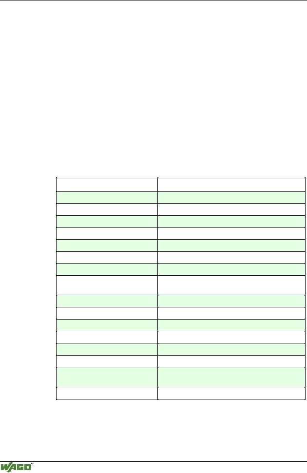
Technical Data:
Item-No.:
Number of outputs
Output current
Number of counters
Input current (internal)
Voltage via power jumper contacts
Signal voltage (0)
Signal voltage (1)
Switching rate
Input current
Counter size
Isolation
Internal bit width
Configuration
Operating temperature
Wire connection
Dimensions (mm) WxHxL
750-404/000-005
2
0.5 A
2
70 mA
DC 24 V (-15 % / + 20 %)
DC -3 V ... +5 V
DC + 15 V ... 30 V
5 kHz max.
(* 2 kHz when the U/D Input is dynamical switched)
5 mA typ.
2x16 Bit Data
500V System/power supply
2x16 Bit Data; 8 Bit control/status
none, or via software with the consent of WAGO
0 °C ... + 55 °C
CAGE CLAMP ; 0.08 mm2 - 2.5 mm2, AWG 28 – 14, 8 – 9 mm Stripped length
12 x 64* x 100, (*from upper edge of carrier rail)
Modular I/O System
ETHERNET TCP/IP