Материал: m012900e
122 • I/O modules
Digital Inputs 750-408, -409
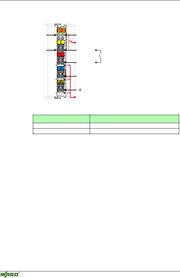
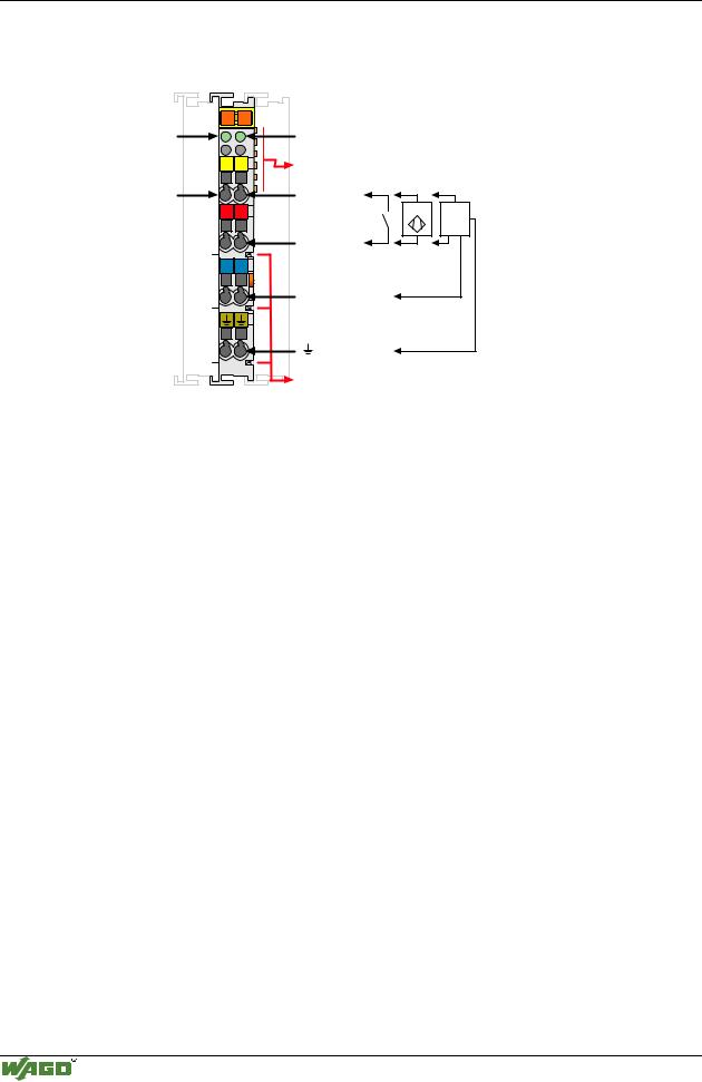
4.2.1.1.11 4 Channel Digital Inputs
(DC 24V, 3.0 ms / 0.2 ms) 750-408, -409
Status |
13 |
14 |
|
|
|
DI 1 |
A |
|
|
C |
|
DI 3 |
B |
|
|
D |
|
|
13 |
14 |
DI 1 |
|
|
|
+ |
+ |
|
- |
- |
|
15 |
16 |
DI 3 |
|
|
|
750-408 |
|
Status
DI 2
DI 4
Data contacts
DI 2
24V
0V
DI 4
Power jumper contacts
Technical description
The power supply is connected to the power jumper contacts on each I/O module for the respective operating voltage. Power connections are made automatically from module to module when snapped onto the DIN rail, with power supplied through a power feed module.
The 4-channel digital inputs are suitable for the direct connection of two 3- conductor sensors (V+, 0V, signal). The power distribution module 750-614 is available for the connection of more sensors to V+ and 0V.
The modules 750-408 and 750-409 are low-side switching (sinking, NPN).
RC filters are series-connected for noise rejection and switch debouncing. They are available with time constants of 3.0 ms and 0.2 ms.
The positions of the different I/O modules in the configured node/station are selectable by the user. A block type configuration is not necessary.
These input modules can operate with all buscouplers of the WAGO-I/O-SYSTEM.
Modular I/O System
ETHERNET TCP/IP
I/O modules • 123
Digital Inputs 750-408, -409
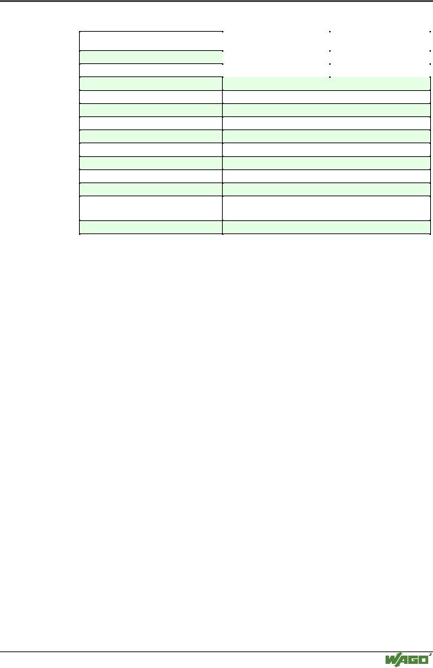
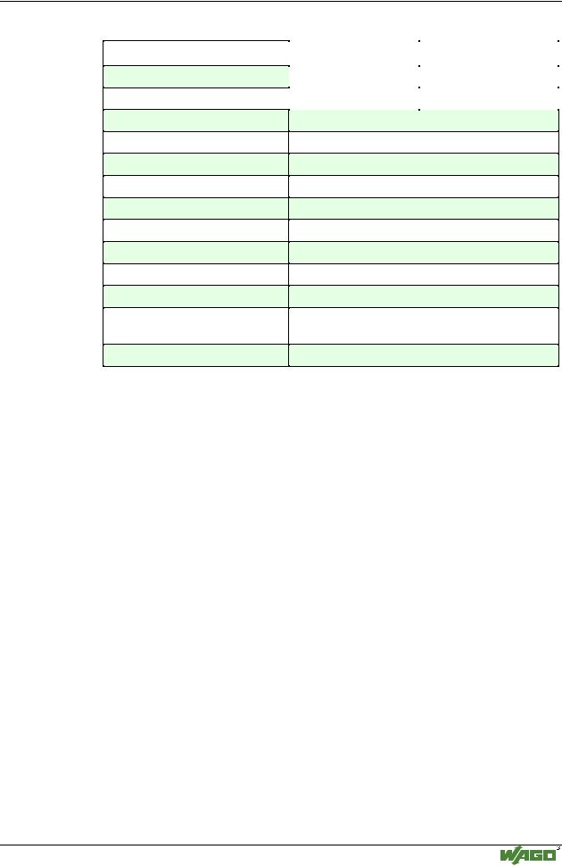
Technical Data:
Item-No.:
Number of inputs
Input filter
Voltage via power jumper contacts
Signal voltage (0)
Signal voltage (1)
Input current (internal)
Input current (field side)
Isolation
Internal bit width
Configuration
Operating temperature
Wire connection
Dimensions (mm) WxHxL
750-408 |
|
750-409 |
|
4 |
|
3 ms |
|
0.2 ms |
DC 24 V (-15% / +20%)
DC 15 V...30 V
DC -3 V...+5 V
10 mA
5 mA typ.
500 V System/power supply
4
no address or configuration adjustment
0°C....+55°C
CAGE CLAMP ; 0.08 mm2 - 2.5 mm2, AWG 28 – 14, 8 – 9 mm Stripped length
12 x 64* x 100 (*from upper edge of carrier rail)
Modular I/O System
ETHERNET TCP/IP
124 • I/O modules
Digital Inputs 750-410, -411
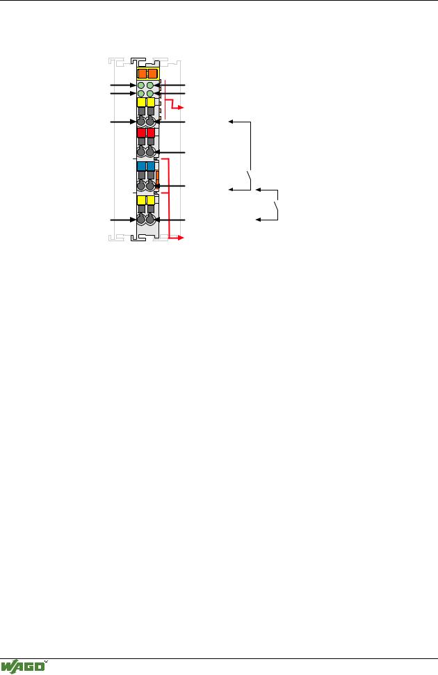
4.2.1.1.12 2 Channel Digital Inputs
(DC 24V, 3.0 ms / 0.2 ms) 750-410, -411
Status |
13 |
14 |
|
|
|
DI 1 |
A |
|
|
C |
|
|
B |
|
|
|
D |
|
13 |
14 |
DI 1 |
|
|
|
+ |
+ |
|
- |
- |
|
750-410 |
|
Status
DI 2
Data contacts
DI 2
+ |
- |
24V |
|
0V |
|
Power jumper contacts |
|
Technical description
The power supply is connected to the power jumper contacts on each I/O module for the respective operating voltage. Power connections are made automatically from module to module when snapped onto the DIN rail, with power supplied through a power feed module.
All 2-channel digital inputs are 4-conductor devices allowing the direct connection of 4-conductor sensors with the terminations V+, 0V, ground and signal.
The 750-410 and 750-411 are optimized for 2 wire proximity switches.RC filters are series-connected for noise rejection and switch debouncing. They are available with time constants of 3.0 ms and 0.2 ms.
The positions of the different I/O modules in the configured node/station are selectable by the user. A block type configuration is not necessary.
These input module can operate with all buscouplers of the WAGO-I/O-SYSTEM.
Modular I/O System
ETHERNET TCP/IP
I/O modules • 125
Digital Inputs 750-410, -411
Technical Data:
Item-No.:
Number of inputs
Input filter
Voltage via power jumper contacts
Signal voltage (0)
Signal voltage (1)
Input current (internal)
Input current (field side)
Isolation
Internal bit width
Configuration
Operating temperature
Wire connection
Dimensions (mm) WxHxL
750-410*) |
750-411*) |
|
2 |
|
|
3 ms |
0.2 ms |
|
|
DC 24 V (-15% / +20%)
DC -3 V...+5 V (std. EN 61131 Type 2)
DC 11 V...30 V (std. EN 61131 Type 2)
2.5 mA max.
8 mA typ.
500 V System/power supply
2
no address or configuration adjustment
0°C....+55°C
CAGE CLAMP ; 0.08 mm2 - 2.5 mm2, AWG 28 – 14, 8 – 9 mm Stripped length
12 x 64* x 100 (*from upper edge of carrier rail)
*) A 2-wire proximity switch can be connected, permissible closed-circuit current ≤ 2 mA
Modular I/O System
ETHERNET TCP/IP