Материал: m012900e

Внимание! Если размещение файла нарушает Ваши авторские права, то обязательно сообщите нам

132 • I/O modules Digital Outputs - Review

4.3 Digital Outputs

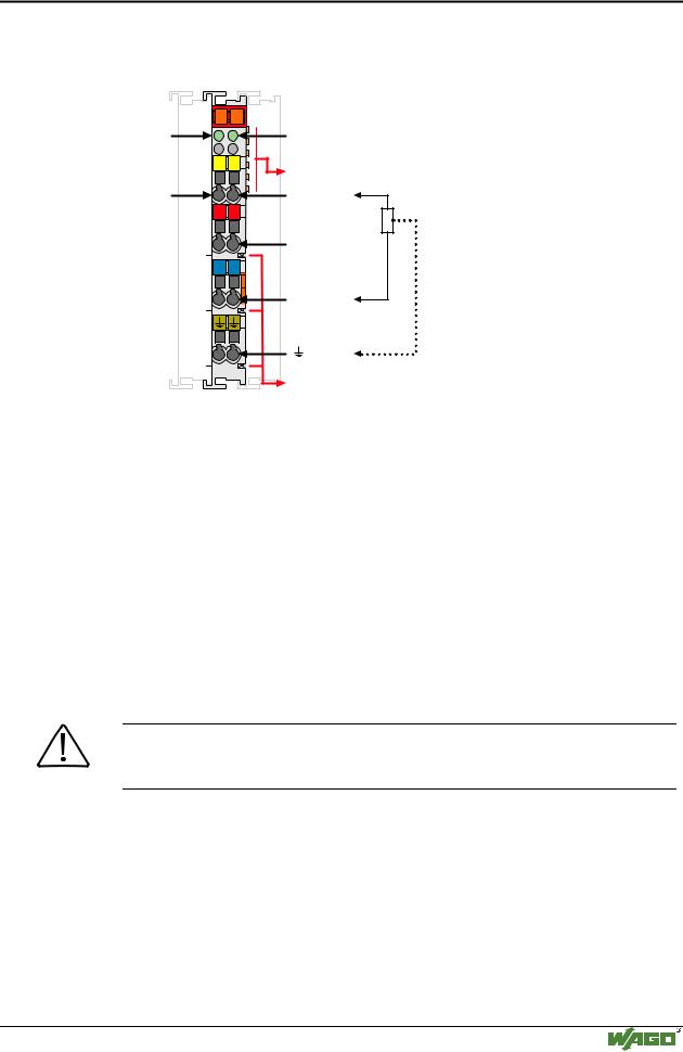
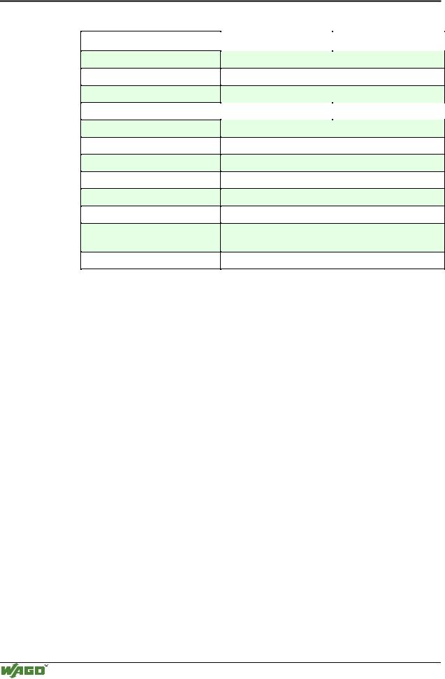
750-501 (2 Channel Digital Output, DC 24 V, 0.5 A)


750-502 (2 Channel Digital Output, DC 24 V, 2.0 A)

page 133


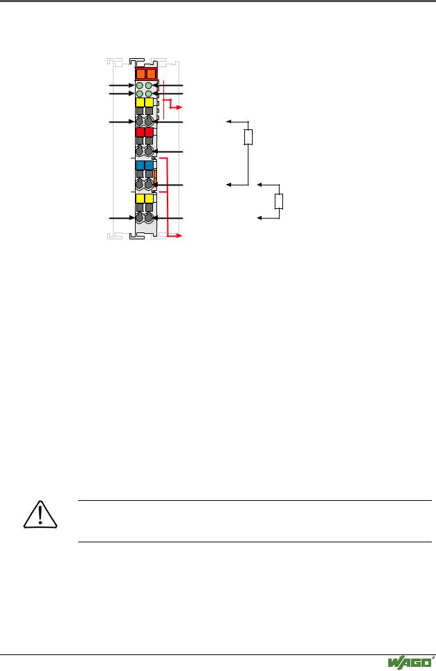
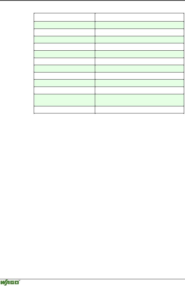
750-504 (4 Channel Digital Output, DC 24 V, 0.5 A)


page 135


750-506 (2 Channel Digital Output, DC 24 V, 0.5 A) diagn.

page 137

750-507 (2 Channel Digital Output, DC 24 V, 2.0 A) diagn.

page 139

750-509 (2 Channel Solid State Relay, 2 Outputs, AC 230 V, 0.3 A) page 142

750-511 (2 Channel Digital Output, DC 24 V, 0.1 A) Pulse width page 144

750-512 (Digital Output Relay, 2 normally open contact non-floating, AC 250 V)

page 150

750-513 (Digital Output Relay, 2 normally open contact isolated outputs, AC 250 V, 2.0 A)

page 153

750-514 (Digital Output Relay, 2 changeover contact isolated outputs, AC 125 V, 0.5 A)

page 156

750-516 (4 Channel Digital Output, DC 24 V, 0.5 A)

page 158

750-517 (Digital Output Relay, 2 changeover contact isolated outputs, AC 230 V, 1.0 A)

page 160

750-519 (4 Channel Digital Output, DC 5 V, 20 mA)

page 162

Modular I/O System

ETHERNET TCP/IP

I/O modules • 133

Digital Outputs 750-501, -502

4.3.1.1.1 2 Channel Digital Outputs

(Standard, DC 24 V, 0.5 A / 2 A) 750-501, -502

13

14

Status


A


DO 1

C

B


D

13

14

DO 1


+

+

-

-

750-501

Status

DO 2

Data contacts

DO 2

24V

0V

Power jumper contacts

Technical description

The power supply is connected to the power jumper contacts on each I/O module for the respective operating voltage. Power connections are made automatically from module to module when snapped onto the DIN rail, with power supplied through a power feed module.

For the digital outputs (without diagnostics) four-conductor devices (V+; 0 V; signal; ground) are standard.

In a node using both two and four channel digital modules, a two channel module must be on the left of a four channel module. The four channel modules do not have a ground connection.

All digital outputs are short-circuit protected.

Attention

In case of overloads a supply module with fuse (750-601) must be connected on the line side to protect the output modules.

The indicated output values have been determined for 100% duty cycle.

However, in case of the 2 A versions it is possible to operate single channels at higher load currents, however always verify that the total current does not exceed 4 A per module. Example: 2x2A (standard); 1x3.5A; 1x0.5A (total current: 4 A).

The positions of the different I/O modules in the configured node/station are selectable by the user. A block type configuration is not necessary.

The output module can operate with all buscouplers of the WAGO-I/O-SYSTEM.

Modular I/O System

ETHERNET TCP/IP

134 I/O modules

Digital Outputs 750-501, -502

Technical Data:

Item-No.:

Number of outputs

Kind of load

Voltage via power jumper contacts

Output current (DC)/per channel

Input current (internal)

Input current (field side)

Isolation

Internal bit width

Configuration

Operating temperature

Wire connection

Dimensions (mm) WxHxL

750-501

750-502

2

resistive, inductive, lamps

DC 24V (-15% / +20%)

0.5 A

2 A


7 mA

15 mA typ. + load

500 V system / power supply

2

no address or configuration adjustment

0°C....+55°C

CAGE CLAMP ; 0.08 mm2 - 2.5 mm2, AWG 28 – 14, 8 – 9 mm Stripped length

12 x 64* x 100 (*from upper edge of carrier rail)

Modular I/O System

ETHERNET TCP/IP

I/O modules • 135

Digital Outputs 750-504

4.3.1.1.24 Channel Digital Outputs (Standard, DC 24 V, 0.5 A) 750-504

Status

13

14

A


DO 1


C

DO 3

B


D


13

14

DO 1


+

+


-

-


15

16

DO 3


750-504

Status

DO 2

DO 4

Data contacts

DO 2

24V

0V

DO 4

Power jumper contacts

Technical description

The power supply is connected to the power jumper contacts on each I/O module for the respective operating voltage. Power connections are made automatically from module to module when snapped onto the DIN rail, with power supplied through a power feed module.

For the digital outputs (without diagnostics) four-conductor devices (V+; 0 V; signal; ground) are standard.

In case of 12 mm wide 4-channel digital output modules it is not possible to use 4-conductor devices. 4 signal outputs, 2xV+ and 2x0V are provided.

In a node using both two and four channel digital modules, a two channel module must be on the left of a four channel module. The four channel modules do not have a ground connection.

All digital outputs are short-circuit protected.

Attention

In case of overloads a supply module with fuse (750-601) must be connected on the line side to protect the output modules.

The indicated output values have been determined for 100% duty cycle.

The positions of the different I/O modules in the configured node/station are selectable by the user. A block type configuration is not necessary.

The output module can operate with all buscouplers of the

WAGO-I/O-SYSTEM.

Modular I/O System

ETHERNET TCP/IP

136 I/O modules

Digital Outputs 750-504

Technical Data:

Item-No.:

Number of outputs

Kind of load

Voltage via power jumper contacts

Output current (DC)/channel

Input current (internal)

Input current (field side)

Isolation

Internal bit width

Configuration

Operating temperature

Wire connection

Dimensions (mm) WxHxL

750-504

4

Resistive, inductive, lamps

DC 24 V (-15% / +20%)

0.5 A short-circuit protected

15 mA

30 mA typ. + load

500 V system / power supply

4

no address or configuration adjustment

0°C....+55°C

CAGE CLAMP ; 0.08 mm2 - 2.5 mm2, AWG 28 – 14, 8 – 9 mm Stripped length

12 x 64* x 100 (*from upper edge of carrier rail)

Modular I/O System

ETHERNET TCP/IP