Материал: m012900e

Внимание! Если размещение файла нарушает Ваши авторские права, то обязательно сообщите нам

I/O modules • 137

Digital Outputs 750-506

4.3.1.1.3 2 Channel Digital Outputs

(Standard with diagnostics, DC 24 V, 0.5 A) 750-506

Status DO 1

Error DO 1

DO 1

13

14

A


C

B


D

13

14

+

+

-

-

750-506

Status DO 2

Error DO 2

Data contacts

DO 2

24V

0V

Power jumper contacts

Technical description

The power supply is connected to the power jumper contacts on each I/O module for the respective operating voltage. Power connections are made automatically from module to when snapped onto the DIN rail, with power supplies through a power feed module.

Using the digital outputs with diagnostic output bits (750-506) allows for verification of the I/O channel by the connected bus.

Example: a short-circuit at the output or an open circuit will set the appropriate error bit true indicating I/O failure. In this configuration the I/O-module includes 2 digital outputs and 2 separate digital inputs. For the digital outputs with diagnostics four-conductor devices (V+; 0V; signal; ground) are standard. All digital outputs are short-circuit protected.

Attention

In case of overloads a supply module with fuse (750-601) must be connected on the line side to protect the output modules.

The positions of the different I/O modules in the configured node/station are selectable by the user. A block type configuration is not necessary.

When using I/O modules with diagnostics, the existing inputs must be considered accordingly in the configuration of the Node/station.

The output module can operate with all buscouplers of the

WAGO-I/O-SYSTEM.

Modular I/O System

ETHERNET TCP/IP

138 I/O modules

Digital Outputs 750-506

Technical Data:

Item-No.:

Number of outputs

Input current (internal)

Voltage via power jumper contacts

Kind of load

Output current

Diagnostics

Isolation

Input current (field side)

Internal bit width

Configuration

Operating temperature

Wire connection

Dimensions (mm) WxHxL

750-506

2

15 mA

DC 24 V (- 15 % / + 20 %)

resistive, inductive, lamps

0.5 A short-circuit protected

open circuit, overload

500 V System/power supply

15 mA typ. + load

4 in; 4 out

without address or configuration adjustment

0 °C ... + 55 °C

CAGE CLAMP ; 0.08 mm2 - 2.5 mm2, AWG 28 – 14, 8 – 9 mm Stripped length

12 x 64* x 100 (*from upper edge of carrier rail)

The output bits control the state of the outputs.

Bit:

Bit 3

Bit 2

Bit 1

Bit 0

Function:

No

No

Controls O2

Controls O1


function

function


The input bits show the state of the output channels.

Bit:


Bit 3


Bit 2


Bit 1


Bit 0

Function:


Diagnostics


Diagnostics


Diagnostics


Diagnostics


O2


O2


O1


O1


output follows output bit:

0

0

0

0

no load is connected:

0

1

0

1

short circuit:

1

0

1

0

power supply too low*:

1

1

1

1

*The diagnostic bits refer to a hysteresis: If the voltage of the field side is higher than 11V in the falling cycle, they are switched on. If the voltage is lower than 15.5 V in the growing cycle, they are switchedoff.

Modular I/O System

ETHERNET TCP/IP

I/O modules • 139

Digital Outputs 750-507

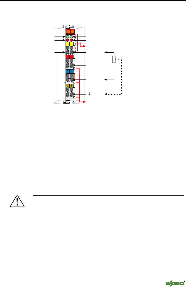
4.3.1.1.4 2 Channel Digital Outputs

(Standard with diagnostics, DC 24 V, 2.0 A) 750-507

Status DO 1

Error DO 1

DO 1

13

14

A


C

B


D

13

14

+

+

-

-

750-506

Status DO 2

Error DO 2

Data contacts

DO 2

24V

0V

Power jumper contacts

Technical description

The power supply is connected to the power jumper contacts on each I/O module for the respective operating voltage. Power connections are made automatically from module to module when snapped onto the DIN rail, with power supplies through a power feed module.

Using the digital outputs with diagnostic output bits (750-507) allows verification of the I/O channel by the connected bus.

Example: a short-circuit at the output or an open circuit will set the appropriate error bit true indicating I/O failure. In this configuration the I/O-module includes 2 digital outputs and 2 separate digital inputs. For the digital outputs with diagnostics four-conductor devices (V+; 0V; signal; ground) are standard. All digital outputs are short-circuit protected

Attention

In case of overloads a supply module with fuse (750-601) must be connected on the line side to protect the output modules.

The positions of the different I/O modules in the configured node/station are selectable by the user. A block type configuration is not necessary.

When using I/O modules with diagnostics, the existing inputs must be considered accordingly in the configuration of the Node/station.

The output module can operate with all buscouplers of the

WAGO-I/O-SYSTEM.

Modular I/O System

ETHERNET TCP/IP

140 I/O modules

Digital Outputs 750-507

Technical Data:

Item-No.:

Number of outputs

Input current (internal)

Voltage via power jumper contacts

Kind of load

Reverse voltage protection

Output current

Short circuit limitation

Open circuit detection

GrenzFrequency

Diagnostics

Isolation

Input current (field side)

Internal bit width

Configuration

Operating temperature

Wire connection

Dimensions (mm) WxHxL

507

2

15 mA

DC 24 V (- 15 % / + 20 %)

resistive, inductive, lamps

yes

2.0 A short-circuit protected

I(scp) 42 A typ.

I(scr) 33 A typ.

II(off) < 30 A typ.

2.5 kHz

Open-circuit, Overload and short circuit

500 V System/power supply

15 mA typ. + load

2 in; 2 out

without address or configuration adjustment

0 °C ... + 55 °C

CAGE CLAMP ; 0.08 mm2 - 2.5 mm2, AWG 28 – 14, 8 – 9 mm Stripped length

12 x 64* x 100 (*from upper edge of carrier rail)

The possibility for diagnostics with 750-507 with each output channel:

Status from PLC to

LED green

LED red

module

(Output)

(diagnostic)

H

ON

OFF


L

OFF

OFF


H

ON

OFF


L

OFF

ON


H

OFF

ON


L

OFF

OFF


H

ON

OFF


L

ON

ON


H

OFF

ON


L

OFF

ON


Description

Output O.K.

OPEN circuit*)

Short circuit with GND*)

Short circuit with +24 V. *)

Overtemperature or Overor Undervoltage *)

*) The full diagnostics is only possible with the status bit and the two LED’s on the module.

Modular I/O System

ETHERNET TCP/IP

I/O modules • 141

Digital Outputs 750-507

The output bits control the state of the outputs.

Bit:

Bit 1

Bit 0

Function:

controls O2

controls O1

The input bits show the state of the outputs.

Bit:


Bit 1


Bit 0

Function:


diagnostics O2


diagnostics O1


output follows output bit:

0

0

no load is connected:

0

1

short circuit:

1

0

power supply too low:

1

1

Modular I/O System

ETHERNET TCP/IP