Материал: m012900e
I/O modules • 147
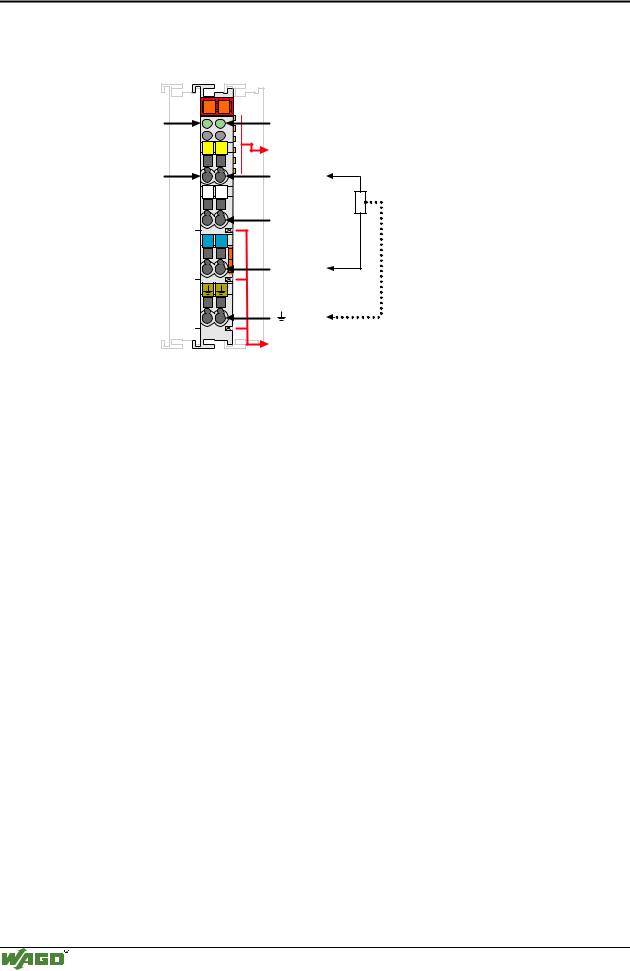
Digital Outputs 750-511
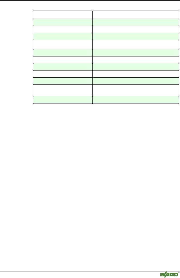
Parameterizing the registers:
The PLC can read and set the registers via the control and status byte and the output bytes in the process image.
Control byte:
Bit |
B7 |
B6 |
|
B5 |
B4 |
B3 |
B2 |
B1 |
B0 |
|
|
|
|
|
|
|
|
|
|
Meaning |
REG |
W/R |
|
0 |
0 |
0 |
0 |
A1 |
A0 |
Status byte: |
|
|
|
|
|
|
|
|
|
|
|
|
|
|
|
|
|
|
|
Bit |
B7 |
B6 |
|
B5 |
B4 |
B3 |
B2 |
B1 |
B0 |
|
|
|
|
|
|
|
|
|
|
Meaning |
REG |
0 |
|
0 |
0 |
0 |
0 |
A1 |
A0 |
REG = 0 Process data exchange
REG = 1 Access to the registers
W/R = 0 Register read mode
W/R = 1 Register write mode
A1..A0 Register address
The output bytes of channel are used for the register values.
Examples for the pulse width bus module 750-511
The following examples illustrate the register read and write modes. The values are binary. In order to make things easier, only the process data of channel 1 is mentioned.
Register 2 read mode
The module is in process date exchange:
Control byte |
Output byte 1 |
Output byte 0 |
|
0xxx xxxx |
xxxx xxxx |
xxxx xxxx |
|
|
|
|
|
Status byte |
|
Input byte 1 |
Input byte 0 |
|
|
|
|
0xxx xxxx |
|
0000 0000 |
0000 0000 |
Register read access is available when bit 7 is set and the register address is entered in the control byte.
Control byte |
Output byte |
1 |
Output byte 0 |
1000 0010 |
Xxxx xxxx |
|
xxxx xxxxx |
Modular I/O System
ETHERNET TCP/IP