144 • I/O modules
Digital Outputs 750-511
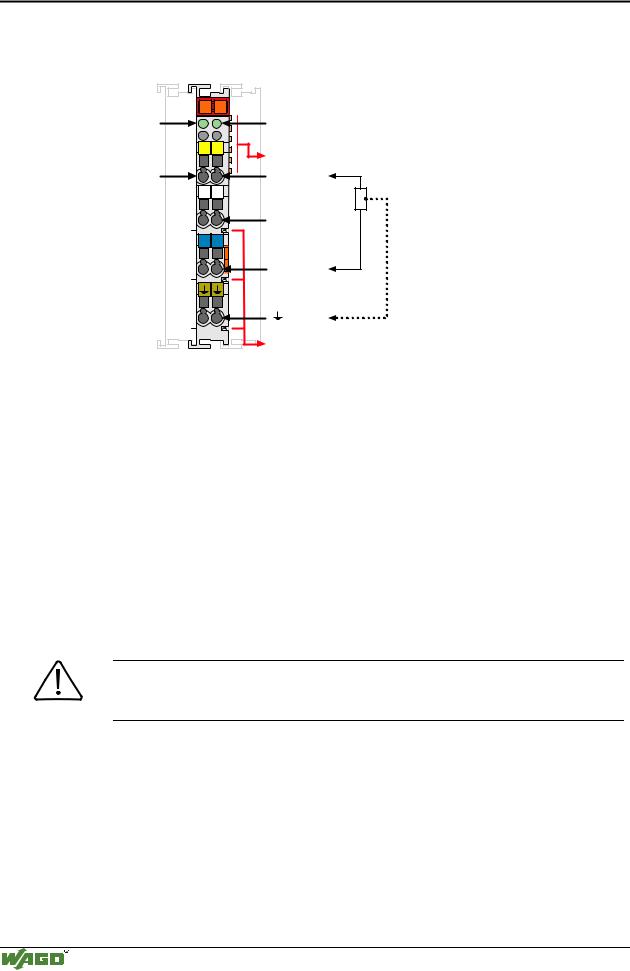
4.3.1.1.6 2 Channel Pulsewidth Module
13 |
14 |
Function |
|
A |
|
DO 1 |
C |
B |
|
|
D |
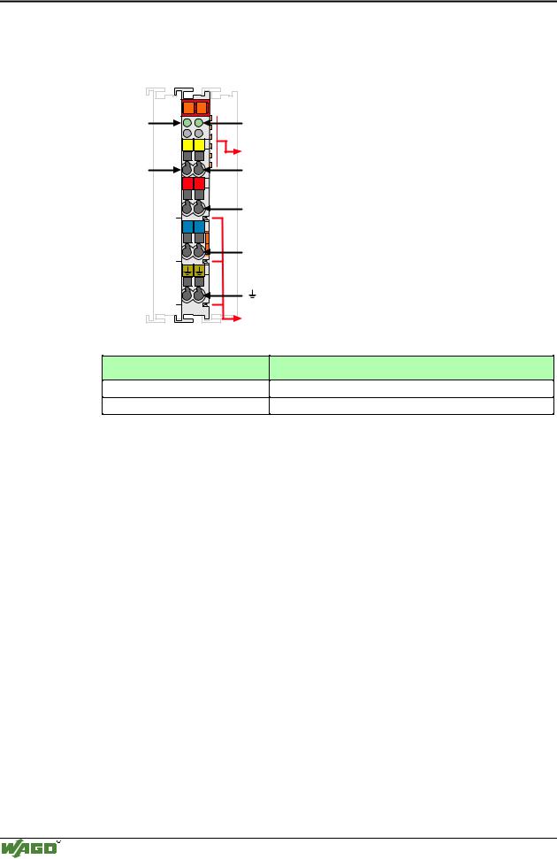
13 |
14 |
DO 1 |
|
+ |
+ |
- |
- |
750-511 |
Function
DO 2
Data contacts
DO 2
24V
0V
Power jumper contacts
I/O modules and variations
Item-No.:
750-511
750-511/000-002
Technical description
Name:
2DO 24V DC 0.1A Pulsewidth
2DO 24V DC 0.1A Pulsewidth 2Hz – 250 HZ
This description is for hard and software version X X X X 2 B 0 2- - - - .
The part number is displayed on the right side of the module.
The initial pre-programmed base frequency is for 250 Hz. The resolution is 10 Bits and the pulsewidth is modulated.
The following description is preliminary and is applicable to the factory configuration.
The pulsewidth output module 750-511 produces a binary modulated signal of 24 V.
The connection of the consuming device should be made between the output and 0 V (common) contacts of the module. The distribution of the 24 V DC is made via the power jumper contacts.
If galvanic isolation is desired, a new power feed via a 750-602 is required.
The PWM module can operate with all buscouplers of the
WAGO-I/O-SYSTEM (except for the economy type).
Modular I/O System
ETHERNET TCP/IP