Материал: m012900e

Внимание! Если размещение файла нарушает Ваши авторские права, то обязательно сообщите нам

152 I/O modules

Digital Outputs 750-512

Relays in the modules 750-512


6ZLWFKLQJ FDSDFLW\


10


AC ohmic


@

DC ohmic


$


>


W

AC inductive, cosϕ =0.4


Q


H


U


U


X


F 1


J


Q


L


K


F


W


L


ZDC inductive L/R=7ms


6


0,1


10

100

1000


6ZLWFKLQJ YROWDJH >9@


7\SLFDO HOHFWULFDO RSHUDWLQJ OLIH

1,E+06


V


Q


R


L


30 V DC ohmic

W


F


D


J


Q


L


120 V AC ohmic

K


F


W


250 V AC ohmsch

L1,E+05


Z


V


30 V DC inductive,

I


R


L/R = 0.7ms

U


H


E


120 V AC inductive,

P


X


cosϕ =0.4

1


1,E+04


250 V AC inductive,

0,1

1

10


6ZLWFKLQJ FXUUHQW >$@

cosϕ =0.4


Modular I/O System

ETHERNET TCP/IP

I/O modules 153

Digital Outputs 750-513

4.3.1.1.8 Digital Output Relay


(2 normally open contacts isolated outputs, AC 250, 2.0 A)

750-513

Status

K1

K2


Relay 1

A


C


B


D


14

24

DO 1


13

23

L 1


750-513

Status

Relay 2

Data contacts

DO 2

L 2

N

Power jumper contact

Technical description

The power supply for the relay coils is not made through the power jumper contacts but directly from the electronics. The respective output contacts of the switching element are therefore always positioned at the field side.

These I/O modules are not provided with integrated power jumper contacts. Care should be taken to supply each isolated module with separate power supply connections.

A connection to ground is made through the series power jumper contact to a power feed module.

The positions of the different modulesin the configured station are the user’s choice. A block type configuration is not necessary.

The output module can operate with all buscouplers of the

WAGO-I/O-SYSTEM.

Modular I/O System

ETHERNET TCP/IP

154 I/O modules

Digital Outputs 750-513

Technical Data:

Item-No.:

Number of outputs

Input current (internal)

Switching voltage Relay

Switching power Relay

Switching current Relay

Isolation

Internal bit width

Configuration

Operating temperature

Wire connection

Dimensions (mm) WxHxL

750-513

2 normally open contacts

100 mA max.

AC 250 V / DC 30 V

500 VA / 60 W, cos ρ =0.4, L/Rmax=7 ms

max

AC/DC 2 A

4 kV System/power supply

2

without address or configuration adjustment

0 °C ... + 55 °C

CAGE CLAMP ; 0.08 mm2 - 2.5 mm2, AWG 28 – 14, 8 – 9 mm Stripped length

12 x 64* x 100 (from upper edge of carrier rail)

Modular I/O System

ETHERNET TCP/IP

I/O modules 155

Digital Outputs 750-513

Relays in the modules 750-513


6ZLWFKLQJ FDSDFLW\


10


@

AC ohmic


$


>


DC ohmic


W


Q


H


U


U

AC inductive, cosϕ =0.4


X


F 1


J


Q


L


K


F


W


L


Z


6


DC inductive L/R=7ms


0,1


10

100

1000


6ZLWFKLQJ YROWDJH >9@


7\SLFDO HOHFWULFDO RSHUDWLQJ OLIH

V1,E+06


Q


R


L


W


F


30 V DC ohmic

D


J


Q


L


K


F


W


120 V AC ohmic

L1,E+05


Z


V


250 V AC ohmsch


I


R


30 V DC inductive,

U


H


L/R = 0.7ms

E


P


X


120 V AC inductive,

1


,E+04


cosϕ =0.4 10

0,1

1


6ZLWFKLQJ FXUUHQW >$@

250 V AC inductive,


cosϕ =0.4

Modular I/O System

ETHERNET TCP/IP

156 I/O modules

Digital Outputs 750-514

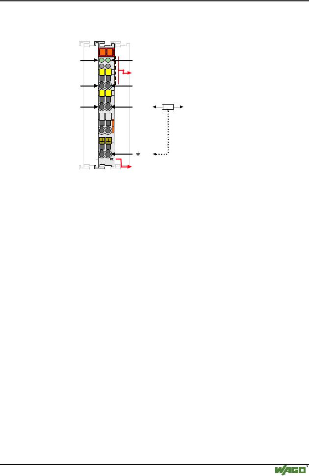
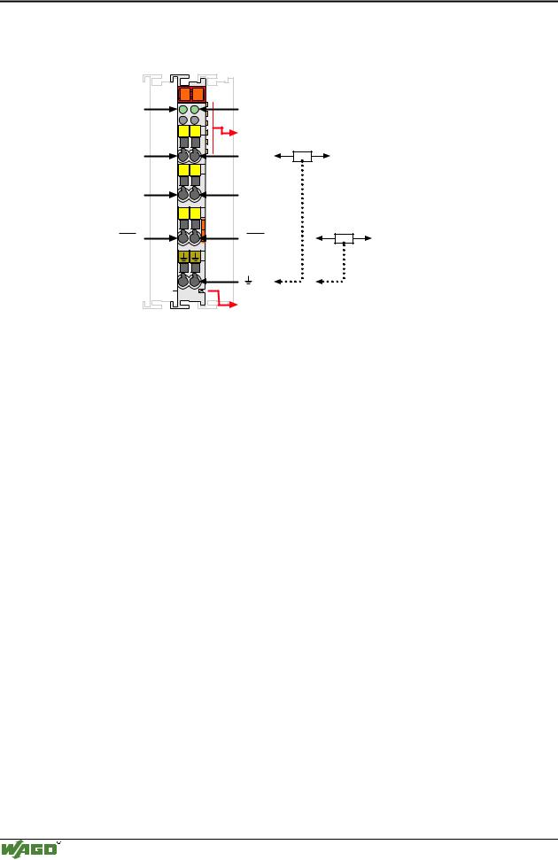
4.3.1.1.9Digital Output Relay

(2 changeover contacts isolated outputs, AC 125 V, 0.5 A) 750-514

Status

K1

K2


Relay 1

A


C


B


D


14

24

DO 1


11

21

L 1


12

22

DO 1


750-514

Status

Relay 2

Data contacts

DO 2

N

L 2

DO 2

N

Power jumper contact

Technical description

The power supply for the relay coils is not made through the power jumper contacts but directly from the electronics. The respective output contacts of the switching element are therefore always positioned at the field side.

These I/O modules are not provided with integrated power jumper contacts. Care should be taken to supply each isolated module with separate power supply connections.

A connection to ground is made through the series power jumper contact to a power feed module.

The positions of the different modules in the configured station are the user’s choice. A block type configuration is not necessary.

The output module can operate with all buscouplers of the

WAGO-I/O-SYSTEM.

Modular I/O System

ETHERNET TCP/IP