158 • I/O modules
Digital Outputs 750-516
4.3.1.1.10 4 Channel Digital Outputs |
|
(Standard, DC 24 V, 0.5 A, sinking output) |
750-516 |
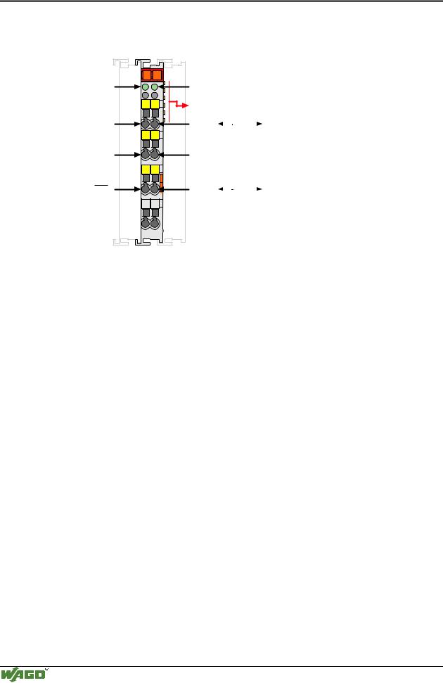
Status |
13 |
14 |
A |
|
DO 1 |
|
|
C |
DO 3 |
B |
|
|
D |
|
13 |
14 |
DO 1 |
|
|
|
+ |
+ |
|
- |
- |
|
15 |
16 |
DO 3 |
|
|
|
750-516 |
Status
DO 2
DO 4
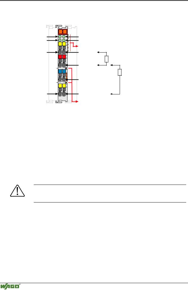
Data contacts
DO 2
24V
0V
DO 4
Power jumper contacts
Technical description
The power supply is connected to the power jumper contacts on each I/O module for the respective operating voltage. Power connections are made automatically from module to module when snapped onto the DIN rail, with power supplied through a power feed module.
For the digital outputs (without diagnostic) four-conductor devices (V+; 0 V; signal; ground) are standard. In case of 12 mm wide 4-channel digital output modules it is not possible to use 4-conductor devices. 4 signal outputs, 2xV+ and 2x0V are provided.
All digital outputs are short-circuit protected.
Attention
In case of overloads a supply module with fuse (750-601) must be connected on the line side to protect the output modules.
The module 750-516 is low-side switching (NPN).
The indicated output values have been determined for 100% duty cycle.
The positions of the different I/O modules in the configured node/station are selectable by the user. A block type configuration is not necessary.
The output module can operate with all buscouplers of the
WAGO-I/O-SYSTEM.
Modular I/O System
ETHERNET TCP/IP