Материал: m012900e
I/O modules • 117
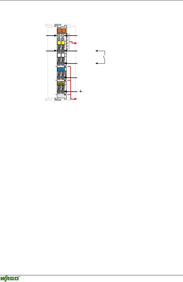
Counter modules 750-404/000-005
Organization of the input and output data:
Attention
For the process data configuration of these bus modules please refer to chapter "Process data architecture for MODBUS/TCP" in the process image description of the corresponding coupler/controller.
The 2 channel rising edge up counter module 750-404/000-005 counts the pulses at Clock1 and Clock2 inputs. The changes from 0 V to 24 V are counted.
The terminals O1 and O2 work as binary outputs. Each output can be activated via specific bits in the CONTROL byte.
The high states of the input and output channels are each indicated by a LED.
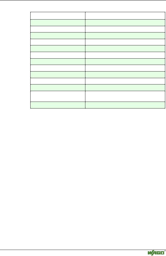
The control byte has the following bits:
Bit |
7 |
Bit |
6 |
Bit 5 |
Bit 4 |
Bit 3 |
Bit 2 |
Bit |
1 |
Bit |
0 |
0 |
|
x |
|
Set coun- |
Set coun- |
Output |
Output |
x |
|
x |
|
|
|
|
|
ter 1 |
ter 2 |
value at |
value at |
|
|
|
|
|
|
|
|
|
|
output O2 |
output O1 |
|
|
|
|
The status byte has the following bits:
Bit |
7 |
Bit |
6 |
Bit 5 |
Bit 4 |
Bit 3 |
Bit 2 |
Bit 1 |
Bit 0 |
x |
|
x |
|
Counter1 |
Counter2 |
Actual |
Actual |
Actual |
Actual |
|
|
|
|
is set |
is set |
signal at |
signal at |
signal at |
signal at |
|
|
|
|
|
|
output O2 |
output O1 |
input Clock |
input Clock |
|
|
|
|
|
|
|
|
2 |
1 |
With the control and Status byte the following tasks are possible:
Setting the counter:
Put Bit 5/4 into the control byte. The counter1/2 with the 32 bit value is loaded into output bytes 0/1 respectively 2/3. As long as the bits are set, the counter can stop and information is stored. The ensuing data of the counter will be conveyed to bit 5/4 of status byte.
Setting the outputs:
Bits 2 and 3 set the additional two outputs of the counter module.
The result of the counter is in binary.
Modular I/O System
ETHERNET TCP/IP
118 • I/O modules
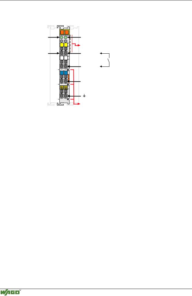
Digital Inputs 750-405
4.2.1.1.9 2 Channel Digital Inputs
(AC 230V) 750-405
Status |
13 |
14 |
|
|
|
DI 1 |
A |
|
|
C |
|
|
B |
|
|
|
D |
|
13 |
14 |
DI 1 |
|
|
|
L |
L |
|
N |
N |
|
750-405 |
|
Status
DI 2
Data contacts
DI 2
230V
N
Power jumper contacts
Technical description
The power supply is connected to the power jumper contacts on each I/O module for the respective operating voltage. Power connections are made automatically from module to module when snapped onto the DIN rail, with power supplied through a power feed module.
All 2-channel digital inputs are 4-conductor devices allowing the direct connection of 4-conductor sensors with the terminations V+, 0V, ground and signal.
The positions of the different I/O modules in the configured node/station are selectable by the user. A block type configuration is not necessary.
These input modules can operate with all buscouplers of the WAGO-I/O-SYSTEM.
Modular I/O System
ETHERNET TCP/IP

I/O modules • 119
Digital Inputs 750-405
Technical Data:
Item-No.:
Number of inputs
Input filter
Voltage via power jumper contacts
Signal voltage (0)
Signal voltage (1)
Input current (internal)
Input current (field side)
Isolation
Internal bit width
Configuration
Operating temperature
Wire connection
Dimensions (mm) WxHxL
750-405
2
10 ms
AC 230 V (-15%/+10%)
AC 0 V..40 V
AC 79 V... 253V
2mA
6.5mA typ.
4 kV System/power supply
2
no address or configuration adjustment
0°C....+55°C
CAGE CLAMP ; 0.08 mm2 - 2.5 mm2, AWG 28 – 14, 8 – 9 mm Stripped length
12 x 64* x 100 (*from upper edge of carrier rail)
Modular I/O System
ETHERNET TCP/IP
120 • I/O modules
Digital Inputs 750-406
4.2.1.1.10 2 Channel Digital Inputs
(AC 120V) 750-406
Status |
13 |
14 |
A |
|
|
|
|
|
DI 1 |
B |
C |
|
|
|
|
|
D |
|
13 |
14 |
DI 1 |
|
|
|
L |
L |
|
N |
N |
|
750-406 |
|
Status
DI 2
Data contacts
DI 2
120V
N
Power jumper contacts
Technical description
The power supply is connected to the power jumper contacts on each I/O module for the respective operating voltage. Power connections are made automatically from module to module when snapped onto the DIN rail, with power supplied through a power feed module.
All 2-channel digital inputs are 4-conductor devices allowing the direct connection of 4-conductor sensors with the terminations V+, 0V, ground and signal.
The positions of the different I/O modules in the configured node/station are selectable by the user. A block type configuration is not necessary.
These input modules can operate with all buscouplers of the WAGO-I/O-SYSTEM.
Modular I/O System
ETHERNET TCP/IP
I/O modules • 121
Digital Inputs 750-406
Technical Data:
Item-No.:
Number of inputs
Input filter
Voltage via power jumper contacts
Signal voltage (0)
Signal voltage (1)
Input current (internal)
Input current (field side)
Isolation
Internal bit width
Configuration
Operating temperature
Wire connection
Dimensions (mm) WxHxL
750-406
2
10 ms
AC 120 V (-15%/+10%)
AC 0 V..20 V
AC 79 V...132V
2mA
4.5mA typ.
4 kV System/power supply
2
no address or configuration adjustment
0°C....+55°C
CAGE CLAMP ; 0.08 mm2 - 2.5 mm2, AWG 28 – 14, 8 – 9 mm Stripped length
12 x 64* x 100 (*from upper edge of carrier rail)
Modular I/O System
ETHERNET TCP/IP