I/O modules • 227
Binary spacer modules 750-622
4.6.1.1.9 Binary spacer modules 750-622
13 |
14 |
A |
|
Operating mode |
C |
B |
|
Input/ |
D |
output |
|
+ |
+ |
- |
- |
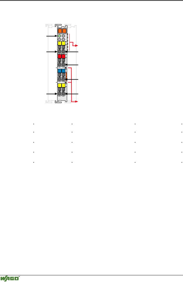
750-622 |
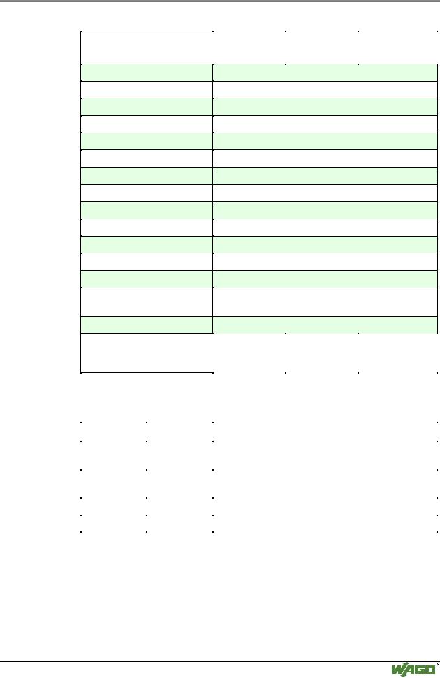
Data width
Data contacts
Supply via power jumper contacts 24V
0V
Power jumper contacts
Technical description
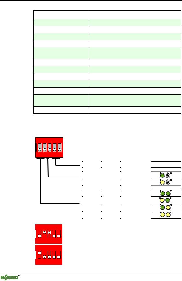
The binary spacer module reserves digital addresses in the WAGO buscoupler.
The number of inputs or outputs can be selected by two DIP switches. 2, 4, 6 or 8 bits are possible (1, 2, 3 or 4-channel modules). A third DIP Switch selects inputs or outputs.
The configuration is indicated by means of 3 LEDs, which are lit, even if there is no voltage applied.
The binary spacer module also works as a 24 V supply module. Power must be connected to supply the modules following the binary spacer.
Modular I/O System
ETHERNET TCP/IP