Материал: m012900e

Внимание! Если размещение файла нарушает Ваши авторские права, то обязательно сообщите нам

I/O modules • 237

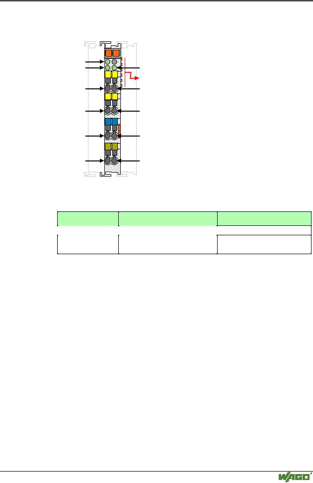
Incremental-encoder-interface 750-631

cumulation register depending upon the status of the overflow or underflow bits.

Setting Counter Position:

The counter can be preset with the CNT_SET bit.

The desired preset is loaded into the data register and the CNT_SET bit is set from 0 to 1. The CNTSET_ACC bit will be set to 1 when the preset value is loaded into the count register.

Maintaining the Present Counter Position:

The encoder present value may be maintained or latched via the external Latch input. First the external latch must be enabled via the EN_LATEXT bit. Once the input is enabled, the data will be latched into the counter module upon a 0 to 1 transition. Upon completion of the latch process the external latch valid bit LATEXT_VAL will be set to 1.

Maintaining a Reference Point:

The storage of a present counter value may also accomplished via the Index pulse from the encoder. First the index latch enable bit must be set, EN_LACT, to a value 1. The encoder present value will be latched upon the low to high transition of the Index input. Upon completion of the data latch process the Index Latch Valid bit, LACT_VAL will be set to 1.

Attention

For the process data configuration of these bus modules please refer to chapter "Process data architecture for MODBUS/TCP" in the process image description of the corresponding coupler/controller.

Modular I/O System

ETHERNET TCP/IP

238 I/O modules

Special terminal blocks - Review

4.8 Special terminal blocks

750-650 (RS232 C9600, n, 8, 1)

page 239

750-651 (TTY-, 20 mA Current Loop)

page 245

750-653 (RS485 Interface)

page 251

750-654 (Data exchange module)

page 257

Modular I/O System

ETHERNET TCP/IP

I/O modules • 239

RS232C interface 750-650

4.8.1.1.1 RS232C Interface

750-650


13

14


Function

A


C


TxD

B


RxD


D


TxD RxD

Data contacts


TxD


RxD


RTSCTS


RTS


CTS


M

M


Common


Common

(ground)


(ground)


S

S


Shield


Shield

(screen)


(screen)


750-650


I/O modules and variations

Item-No.: Description

750-650

RS 232 C Interface 9600,n,8,1

750-650/000-001 RS 232 C Interface 9600,n,8,1

5 Byte

Name

RS 232 C/ 9600/ N/ 8/ 1

RS 232 C/ 9600/ N/ 8/ 1/ 5BYTE

Technical description

This technical description is only valid for hardware and software versions X X X X 2 C 0 3----. The product series number is printed on the right side of the module.

The following description is preliminary and is applicable to the factory preset configuration.

Many other operational modes are possible (please contact WAGO for the corresponding settings).

The interface module can operate with all WAGO-I/O-SYSTEM buscouplers (except for the economy type).

Modular I/O System

ETHERNET TCP/IP

240 I/O modules

RS232C interface 750-650

Technical Data:

Item-No.:

Transmission channel

Transmission rate

Bit skew

Bit transmission

Resistance

Current consumption (internal)

Transmission length

Input buffer

Output buffer

Voltage supply

Isolation

Internal bit width

Configuration

Operating temperature

Wire connection

Dimensions (mm) WxHxL

Presetting:

Baud rate

Internal bit width

750-650,

750-650/000-001

2 (1/1), T x D and R x D, full duplex

1200 - 19200 Baud

< 3 %

-

-

50 mA max.

max. 15 m RS 232 cable

128 Byte

16 Byte

via internal system supply

500 V System/power supply

1 x 40 Bit, 1 x 8 Bit control/status

none, or via software with the consent of WAGO

0 °C ... + 55 °C

CAGE CLAMP ; 0.08 mm2 - 2.5 mm2, AWG 28 – 14, 8 – 9 mm Stripped length

12 x 64* x 100 (*from upper edge of carrier rail)

9600 Baud

1 x 24 Bit in/out, 1 x 8 Bit Control/Status

Description of RS 232:

The interface module is designed to operate with all WAGO I/O fieldbus couplers. The serial interface module allows the connection of RS 232-Interface devices to the WAGO I/O SYSTEM. The RS 232 Interface module can provide gateways within the fieldbus protocol. This allows serial equipment such as printers, barcode readers, and links to local operator interfaces to communicate directly by the fieldbus protocol with the PLC or PC Master.

This module does not support a higher level protocol. Communication is made completely transparent to the fieldbus allowing flexibility in further applications of the serial interface module. The communication protocols are configured at the Master PLC or PC.

The 128 byte input buffer provides for high rates of data transmission. When using slower transmission speeds, you can collect the received data with lower priority without loosing data.

The 16 byte output buffer provides for faster transmission of larger data strings.

Modular I/O System

ETHERNET TCP/IP

I/O modules • 241

RS232C interface 750-650

Attention

The data transmission takes place at 9,600 baud (default value). 1 start bit, 8 data bits and 1 stop bit will be transmitted. No parity is available. The user controls data via the RTS and CTS signals. These signals are generated in the module depending on the loading status of the buffers. These controls can be deactivated by means of an external jumper. RTS and CTS are to be connected.

Attention

For testing purposes the Windows terminal emulation can be used. A cable with a 9- pole sub-D socket is required. Pin 5 is connected to input "common". Pin 2 is connected to TxD and Pin 3 to RxD. RTS and CTS of the module are connected. A hardwarehandshake between the terminal emulation and the PLC is not possible.

Organization of the inand output data:

The module is a combined analog input and output module with 2 x 16 bit input and output data. The transfer of the data to be transmitted and the received data is made via 3 output and 3 input bytes. One control byte and one status byte are used to control the floating data.

Requests are indicated by a change of a bit. An assigned bit indicates execution by adopting the value of the request bit.

Up to 3 characters which have been received via interface can be stored in the input bytes 0 to 2. The output bytes will contain the characters to be sent.

The control byte consists of the following bits:

Bit 7

0

Constant value should always be 0.

Bit 6

Bit 5

Bit 4

OL 2

OL1

OL0

Frames available in output area OL2 is always 0,

i.e. OL2, OL1, OL0 = 0,1,1

3 characters should be sent and put into the output.

Bit 3

Bit 2

Bit 1

Bit 0

0

IR

RA

TR

Constant

Initialization

Receive

Transmit

value

request

acknow-

request

should


ledge


always


be 0.


The status byte has the following bits:

Bit 7

0

Constant value should always be 0.

Bit 6

Bit 5


Bit 4

Bit 3

Bit 2

Bit 1

Bit 0

IL2

IL1


Il0

BUF_F

IA

RR

TA

Frames available in input area

Input

Initialization

Receive

Transmit


IL2 is always 0.


buffer is

acknowledge

request

acknow-

i.e. IL2, IL1, IL0 = 0,1,0

full.


ledge

2 characters were received and


reside in input 0 and input 1.


The PLC/PC is able to control transmission and reception of data by means of the control byte and the status byte.

Modular I/O System

ETHERNET TCP/IP