Материал: m012900e

Внимание! Если размещение файла нарушает Ваши авторские права, то обязательно сообщите нам

232 I/O modules

SSI transmitter interface 750-630

The resolution of the sensor depends upon the configuration of the sensor and the physical number of revolutions in the motion profile. Since the basis of the encoder is to provide absolute positional information, which is based upon a mechanical configuration limited to one revolution or less, the maximum resolution of this module is 24 bit.

The frequency of the data signal input to the SSI module is maintained at 125 kHz.

Listed below are the recommended cable lengths for the various clock signal Baud rates

Baud rate

100 kHz

125 kHz

200 kHz

300 kHz

400 kHz

max. Cable length

400 m

300 m

200 m

100 m

50 m

Attention

For the process data configuration of these bus modules please refer to chapter "Process data architecture for MODBUS/TCP" in the process image description of the corresponding coupler/controller.

Modular I/O System

ETHERNET TCP/IP

I/O modules • 233

Incremental-encoder-interface 750-631

4.7.1.1.2 Incremental encoder interface 750-631


13

14

15

16


A

A


A


C


C


C


Latch

B


B


B


D


D

Gate


A

A

Ue

Uo


A


0V

A


+

+

5V

B

B


B


24V


B


C

C

-

-


C


0V


C


L

G

S

S


Latch


Gate


750-631


I/O modules and variations


Item-No.:

Description

Name

750-631

Incremental encoder-interface

Increment. Enc.


4 times sampling


750-631/000-001

Incremental encoder-interface

Increment. Enc./Single Interpret.


1 time sampling


Technical description

Attention

The description that is in the I/O ring binder data pages (888-543/020-101 dated 4/96) is not correct.

This technical description is only valid for hardware and software versions X X X X 2 B

0 1----. The product series number is printed on the right side of the module.

The described operational mode is 4 times or quadrature sampling.

The following description is preliminary and is applicable to the factory configuration.

The Quadrature Encoder Interface can operate with all WAGO-I/O-SYSTEM buscouplers (except for the economy type).

Modular I/O System

ETHERNET TCP/IP

234 • I/O modules Incremental-encoder interface 750-631

Technical Data:

Item-No.:

Encoder connections

current consumption (internal)

Sensor supply Voltage

Data word

Maximum Frequency

Quadraturdecoder

Data Latch word

Commands

Supply Voltage

Input current (internal)

Sensor output current

Internal bit width

Configuration

Operating temperature

Wire connection

Dimensions (mm) WxHxL

Default configuration

750-631 750-631/000-001

A, A (inv), B, B (inv), C, C (inv)

25 mA

DC 5 V

16 Bit Binary

1 MHz

1-2-4 times sampling

16 Bit

read, reset, start

DC 24 V (- 15 % / + 20 %)

85 mA typ. without sensor

300 mA max.

1 x 32 Bit Data, 1 x 8 Bit control/status

none, or via software with the consent of WAGO

0 °C ... + 55 °C

CAGE CLAMP ; 0.08 mm2 - 2.5 mm2, AWG 28 – 14, 8 – 9 mm Stripped length

24 x 64* x 100 (*from upper edge of carrier rail)

4 times sampling

1 times sampling


Operational Characteristics:

The quadrature encoder interface accepts up to two input signals for the counting increment. The index pulse may also be considered should the control configuration require it. There is also a Latch and Gate input available on the module for added functionality.

The quadrature encoder provides two signals that are shifted 90 degrees from each other, signals A and B. In order to achieve a better common mode noise rejection ratio, the output signals from the encoder are transmitted via a differential signal. Their complement signals, A(inv.) and B(inv.) are also transmitted. A directional determination may be made by which signal leads. If the A signal leads, the direction is considered to be forward. If the B signal leads, the direction is considered to be reverse.

By exchanging the A and A(inv.) the phase relationship will be changed by 180 degrees, thus allowing the direction to be preset via the wiring configuration.

Modular I/O System

ETHERNET TCP/IP

I/O modules • 235

Incremental-encoder-interface 750-631

Most quadrature encoders have an Index signal, or Z rev, as well as the incremental signal. This signal provides one pulse per revolution with a duration equal to an incremental pulse.

The inputs to the quadrature encoder module must be supplied from an encoder with Line Driver Outputs for proper operation. The 5 Volt DC output may be used to power the encoder. The 24 Volt DC input supply must be provided from an external power supply.

The Gate and Latch inputs are 24 Volt DC.

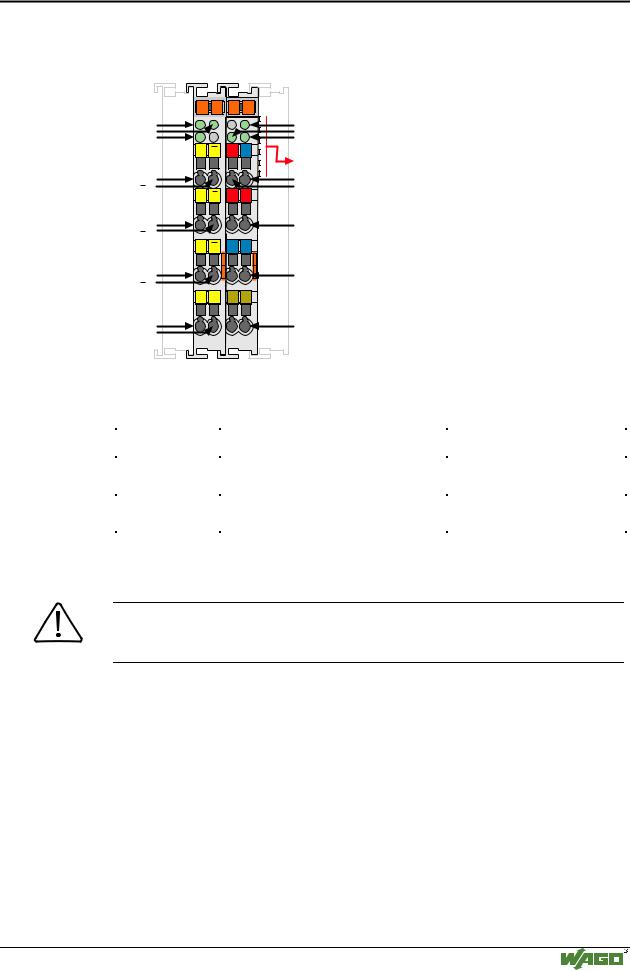
Module Inputs and Outputs:

Input

Type

Function

Signal A and

Input, TTL

Incremental pulse signals for channel A

Signal -A


Signal B and

Input, TTL

Incremental pulse signals for channel B

Signal -B


Signal C and

Input, TTL

Index pulse signals

Signal -C


Shield

Input

Shield connection for encoder wiring

Sensor 0V

Output

Supply return for encoder supply

Sensor +5V

Output

5 Volt DC supply for encoder

+24V

Input

24 Volt DC supply, field connection

0V

Input

Supply return, field connection

Gate

Input, 24V

24 Volt DC input for gate signal

Latch

Input, 24V

24 Volt DC input for Latch signal

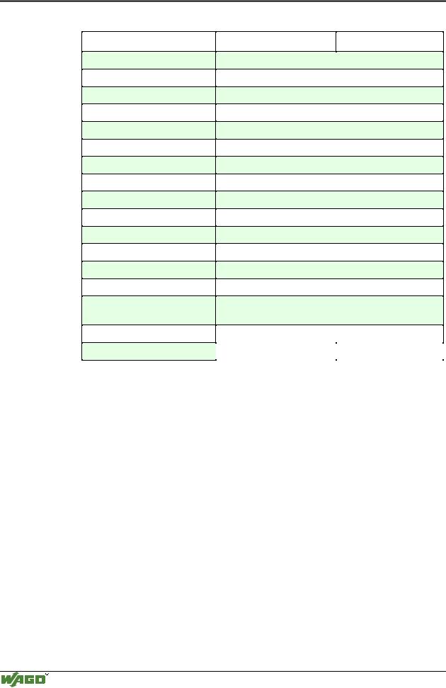
The Input Gate stops the counter. Only 0 V or an open connection will initialize the counter.

24 V stops the counting process.

The input Latch controls the writing of the actual counter value into the Latch register. This input is activated by the control bit EN_LATEXT ("1"). EN_LACT has to be deactivated ("0"). The first change from 0 V to 24 V at the Latch input writes the actual counter value into the Latch register.

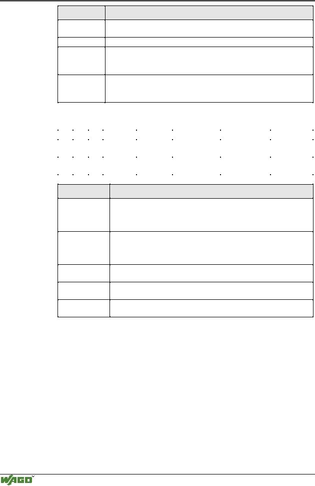
The control byte has the following bits:

Bit 7

Bit 6

Bit 5

Bit 4

Bit 3

Bit 2

Bit 1

Bit 0

0

x

CFAST_M

x

x

CNT_SET

EN_LATEXT

EN_LATC

0

x

Operating

x

x

Counter set

Release Latch

Release


mode


Index Pulse

Please note Bit 7 is a reserved bit and must always be set to 0. It is responsible for register communication which is not described in this chapter.

Modular I/O System

ETHERNET TCP/IP

236 • I/O modules Incremental-encoder interface 750-631

Bit

CFAST_M

CNT_SET

EN_LATEXT

EN_LACT

Function

Fast mode operation. Only the counter module function will be operable. All other control bits will be ignored.

The counter module will be preset to a count value with a rising edge.

0 =The external latch input is deactivated.

0 to 1=The module will latch in the counter data on the first rising edge.

Other changes have no effect.

0 =Latching data with the Index pulse is deactivated.

0 to 1=The Index pulse will latch in the counter data on the first rising edge.

Other changes have no effect.

The status byte contains the information as listed below.

Bit7

Bit6

Bit5

Bit4

Bit3

Bit2

Bit1

Bit0

0

x

x

OVER-

UNDER-

CNTSET_ACC

LATEXT_VAL

LATC_VAL


FLOW

FLOW


0

x

x

Counter

Counter

Counter Set

External Latch

Latch Data


Overflow

Underflow

Acknowledge

Acknowledge

Set

Bit

OVERFLOW

UNDERFLOW

CNTSET_ACC

LATEXT_VAL

LACT_VAL

Function

The Overflow bit will be set if the counter value rolls over from 65535 to 0. This bit will automatically be reset if the counter passes through more than one third of the count range, 21845 to 21846, or if an Underflow occurs.

The Underflow bit will be set if the counter value rolls back from 65535 to 0. This bit will automatically be reset if the counter passes through more than two thirds of the count range, 43690 to 43689, or if an Overflow occurs.

The Counter Set Acknowledge bit is set when a valid counter value is preset to the module.

The Latch External Valid Acknowledge bit is set when a counter value is latched into the module via the Latch input.

The Latch Index Pulse Valid Acknowledge bit is set when a counter value is latched into the module via the Index pulse.

It is possible to process and/or check the actions listed below via the control and status bits

Extending the 16 bit counting range:

The internal counting range is 16 bits or a maximum value of 65535. Should the application require an extended count range the location-difference- integration method may be employed. This method uses the control system to store the encoder module value. Any new encoder value will have the previously stored encoder value subtracted from it. This value will then be added to an accumulated register value. It is assumed that the encoder value difference of the two encoder values is smaller than 16 bits therefore overflows need not be considered.

Another method calculates the extended encoder range via the underflow and overflow status bits. The encoder value is either added or subtracted to the ac-

Modular I/O System

ETHERNET TCP/IP