Материал: m012900e

Внимание! Если размещение файла нарушает Ваши авторские права, то обязательно сообщите нам

I/O modules

Supply and End modules – Review 217

4.6 Supply and End modules

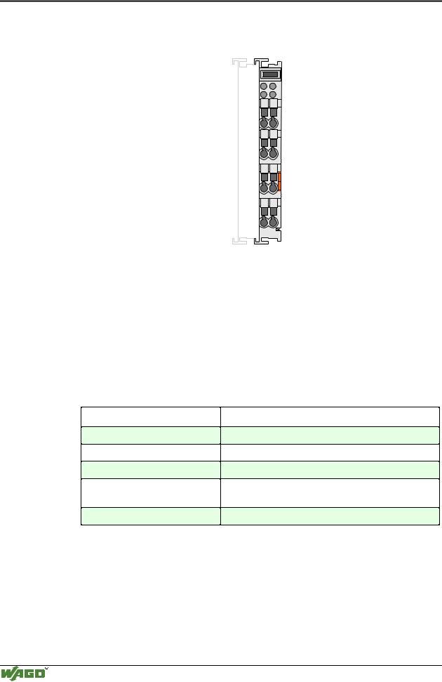
750-600 (End module)

page 218

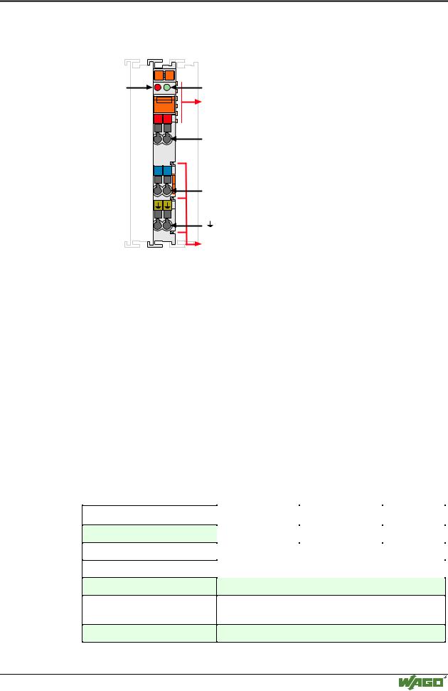
750-601 (Supply modules with fuse holder, AC 24V) 750 -609 (Supply modules with fuse holder, AC 230V) 750-615 (Supply modules with fuse holder, AC 120V)

page 219

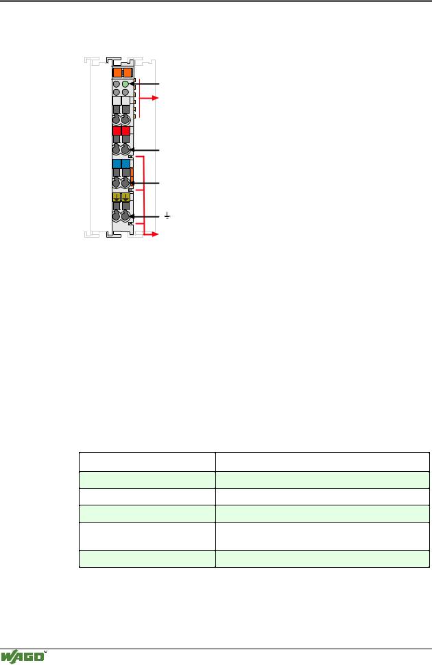
750-602 (Supply modules, passive DC 24 V)

page 220

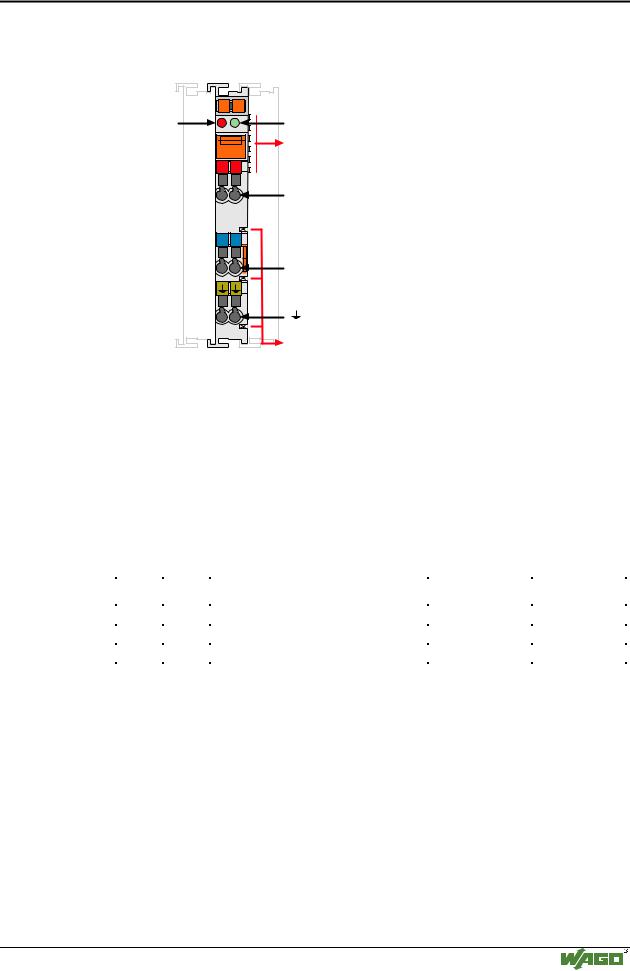
750-610 (Supply modules with fuse holder,with diagn., DC 24 V) 750-611 (Supply modules with fuse holder,with diagn., AC 230 V)

page 221

750-612 (Supply modules, passive, AC/DC 230 V)

page 223

750-613 (Supply modules with DC-DC converter, DC 24 V)

page 224

750-614 (Potential multiplication modules, AC/DC 24 V-230 V) page 225

750-616 (Separation modules)

page 225

750-622 (Binary spacer modules)

page 227

Modular I/O System

ETHERNET TCP/IP

218 • I/O modules End module 750-600

4.6.1.1.1 End module 750-600

A

C

B

D

750-600

Technical description

After the fieldbus node is assembled with the correct buscoupler and selected I/O modules, the end module is snapped onto the assembly. It completes the internal data circuit and ensures correct data flow. This module is a necessary component to all WAGO fieldbus nodes.

Technical Data:

Item-No.:

Voltage

Current via contacts

Operating temperature

Wire connection

Dimensions (mm) WxHxL

750-600

-

-

0 °C ... + 55 °C

CAGE CLAMP ; 0.08 mm2 - 2.5 mm2, AWG 28 – 14, 8 – 9 mm Stripped length

12 x 64 x 100, (from upper edge of carrier rail)

Modular I/O System

ETHERNET TCP/IP

I/O modules

Supply modules 750-601, -609, -615 • 219

4.6.1.1.2 Supply modules

(DC 24V / AC 230V / AC 120V) 750-601, -609, -615

13

14

Error


A


fuse blown

B

T 6,3 A

250 V

+

+

-

-

750-601

Status voltage supply

Data contacts

Supply via

power jumper contacts 24V

0V

Power jumper contacts

Technical description

The supply module feeds field power through the power jumper contacts. Maximum current supply to the modules with fuse holder is 6.3 A. Should more current be needed, additional supply modules may be added in the assembly.

The modules 750-601, 609 and 615 are additionally equipped with a fuse. Changing the fuse is accomplished by pulling out the fuse holder and removing the fuse.

A blown fuse is indicated by a red LED.

Make sure the proper voltage is applied to the supply module. Use caution when changing voltage potential within a node. All modules following the supply module will be powered at the new potential. The following table shows the voltage ratings for the supply modules.

Technical Data:

Item-No.:

Voltage

Current via contacts

Fuse

Operating temperature

Wire connection

Dimensions (mm) WxHxL

750-601

750-609

750-615

DC 24 V

AC 230 V

AC 120 V


max. 6.3 A


5 x 20, 6.3 A


0 °C ... + 55 °C

CAGE CLAMP ; 0.08 mm2 - 2.5 mm2, AWG 28 – 14, 8 – 9 mm Stripped length

12 x 64 x 100, (from upper edge of carrier rail)

Modular I/O System

ETHERNET TCP/IP

220 I/O modules

Supply modules 750-602

4.6.1.1.3 Supply modules

(DC 24V, passive) 750-602

13

14

A


C

B


D

+

+

-

-

750-602

Status voltage supply -Power jumper contacts 1)

Data contacts

Supply via power jumper contacts 24V

0V

Power jumper contacts

1) only for 750-602

Technical description

The supply module feeds field power through the power jumper contacts. Maximum current supply to all connected modules is 10 A. Should more current be needed, additional supply modules may be added in the assembly.

Make sure the proper voltage is applied to the supply module. Use caution when changing voltage potential within a node. All modules following will be powered at the new potential.

Technical Data:

Item-No.:

Voltage

Current via contacts

Operating temperature

Wire connection

Dimensions (mm) WxHxL

750-602

DC 24 V

Max. DC 10 A

0 °C ... + 55 °C

CAGE CLAMP ; 0.08 mm2 - 2.5 mm2, AWG 28 – 14, 8 – 9 mm Stripped length

12 x 64 x 100, (from upper edge of carrier rail)

Modular I/O System

ETHERNET TCP/IP

I/O modules 221

Supply modules 750-610, -611

4.6.1.1.4Supply modules

(DC 24V / AC 230V) 750-610, -611

13

14

Error


A


fuse blown

B

T 6,3 A

250 V

+

+

-

-

750-610

Technical description

Status voltage supply

Data contacts

Supply via

power jumper contacts 24V

0V

Power jumper contacts

The supply module feeds field power through the power jumper contacts. Maximum current supply to the modules with fuse holder is 6.3 A. Should more current be needed, additional supply modules may be added in the assembly.

Changing the fuse is accomplished by pulling out the fuse holder and removing the fuse. A blown fuse is indicated by a LED.

The 750-610 and 611 modules send information about the status of the supply module to the fieldbus coupler through two digital input bits.

Bit 1

Bit 2

Description

750-610

750-611

0

0

Voltage under:

DC 5 V

AC 40 V

1

0

Fuse blown


0

1

Fuse o.k., Voltage over:

DC 15 V

AC 164 V

Make sure the proper voltage is applied to the supply module. Use caution when changing potential within the node. All modules following the supply module will be powered at the new potential. The following table shows the voltage ratings for the supply modules.

Modular I/O System

ETHERNET TCP/IP