Материал: Sb97789
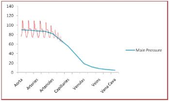
Fig. 1. Pressure changes on blood vessels
Blood pressure monitor operating principle
Blood pressure monitor operation is based on the oscillometric method. This method takes advantage of the pressure pulsations taken during measurements. An occluding cuff is placed on the left arm and is connected to an air pump and a pressure sensor. Cuff is inflated until a pressure greater than the typical systolic value is reached, then the cuff is slowly deflated. As the cuff deflates, when systolic pressure value approaches, pulsations start to appear. These pulsations represent the pressure changes due to heart ventricle contraction and can be used to calculate the heartbeat rate. Pulsations grow in amplitude until mean arterial pressure (MAP) is reached, then decrease until they disappear.
Oscillometric method determines the MAP by taking the cuff pressure when the pulse with the largest amplitude appears. Systolic and diastolic values are calculated using algorithms that vary among different medical equipment developers. Freescale Blood Pressure Monitor calculates the systolic and diastolic pressure by considering that systolic pressure is approximately equal to the pressure measurement taken in the cuff when a pulse with 70% of the amplitude of the MAP pulse appears while the cuff pressure is above the MAP value. Diastolic pressure is approximately equal to the cuff pressure value registered when a pulse with 50% of the MAP pulse amplitude appears while the cuff pressure is under the MAP value.
Blood pressure monitor implementation
Blood pressure monitor is implemented using Freescale medical-oriented Kinetis K53 MCUs and Flexis MM devices, which feature the following characteristics:
•16-bit ADC;
•12-bit DAC;
•2x programmable gain operational amplifiers (OpAmps);
•2x transimpendance amplifiers (TRIAMPS);
26
•Vref generator;
•Set of DSP instructions including MAC (Only K5X Family);
•Multiply and Accumulate (MAC) instruction on MCF51MM.
Freescale medical-oriented MCUs reduce the Bill Of Materials (BOM) required for medical applications and provide great processing capabilities ideal for medical equipment. Nevertheless, some external circuitry is needed for pressure sensing and cuff control.
MED-BPM analog front end
MED-BPM Analog Front End (AFE) is a demo board designed for work as a blood pressure monitor in conjunction with a Freescale medical-oriented MCU. MED-BPM communicates with the MCU using the medical connector, and allows for easy prototyping and reduced time to market by using the Freescale Tower System.
Arm cuff pressure control
MED-BPM works using an oscillometric method for blood pressure measurements. This is a noninvasive method which requires an external arm cuff in order to occlude the patient’s arm and detect the systolic and diastolic arterial pressure. The arm cuff is inflated using an external air pump controlled with an MCU GPIO pin, and deflated by activating an escape valve with another GPIO pin. Because the current provided by the USB port (500 mA) is not enough to activate the air pump and the valve (600 mA), those external components are activated by using an external power source which provides sufficient current. An optocoupler is needed for coupling MCU control signals with the components to activate.
Output from the optocoupler is connected to a MOSFET working as a switch, so the air pump and valve mechanisms can be activated successfully.
Signal filtering and amplification
This stage is composed of three filters, one buffer circuit, and one noninverting amplifier.
Filters are first order RC passive type, and the cut-off frequency is described by the following formula.
1.A signal is passed through a 10 Hz RC low-pass filter (LPF) composed of a resistor and a capacitor in order to remove high-frequency noise.
2.Then the signal is passed through a buffer circuit consisting of a single OpAmp in buffer mode to couple the signal to the sensor. The output from the buffer circuit is where the arterial pressure measurements are taken.
27
3.The signal is then filtered again with a 2.2 Hz RC high-pass filter which removes high-frequency noise and gets a cleaner signal for amplification.
4.This signal is amplified using a non-inverting amplifier composed by a second Op-Amp and two resistors, (100 kΩ and 1 kΩ) generating a gain of 101 so cuff oscillations can be distinguished better.
5.After this stage, the signal is filtered again with another 10 Hz RC LPF so high-frequency noise can be removed.
Задания к тексту:
1.Выпишите ключевые слова. Разделите их на две группы – профессиональной лексики и общетехнической. Отберите самые важные для описания содержания статьи.
2.Найдите в тексте статьи предложения, содержащие грамматические обороты с инфинитивом, герундием, причастием в активном и пассивном залоге. Объясните особенности их использования и перевода.
3.В чем заключается научная новизна исследования?
4.Подготовьте свой вариант заключения представленного в статье мате-
риала.
28
Тема 3. Глюкометр
Задание 1.Прочитайте аннотацию. Составьте глоссарий слов и выражений, которые, на ваш взгляд, могут встретиться в статье, посвященной данной теме.
This tutorial introduces the different types of glucose meters. It explains the different types of calibration used for test-strips, and discusses other variables that designers must consider when selecting products.
Задание 2. Ознакомьтесь со вступительной частью статьи. Что вы знаете о глюкометрах? Какие они бывают? Для чего нужны глюкометры? Какие могут быть усовершенствования в производстве глюкометров?
Blood glucose meters and other home medical devices today are small, portable, and easy to use. The mark of a good meter is one that the patient will use regularly and that returns accurate and precise results. Over the past few years the trend with blood glucose meters has been to maximize patient comfort and convenience by reducing the volume of the blood sample required. The blood sample size is now small enough that alternate-site testing is possible. This eliminates the need to obtain blood from the fingers and greatly reduces the pain associated with daily testing. Accurate and precise results have been increased by using better test strips, electronics, and advanced measurement algorithms. Other conveniences include speedy results, edge fill strips, and illuminated test strip ports, to name just a few.
Задание 3. Прочитайте всю статью. Переведите ее и перескажите основное ее содержание. Сформулируйте выводы.
Blood Glucose Meter
There are continuous and discrete (single-test) meters on the market today, and implantable and noninvasive meters are in development. Continuous meters are by prescription only and use a subcutaneous electrochemical sensor to measure at a programmed interval. Single-test meters use electrochemical or optical reflectometry to measure the glucose level in units of mg/dL or mmol/L.
The majority of blood glucose meters are electrochemical. Electrochemical test strips have electrodes where a precise bias voltage is applied with a digital-to- analog converter (DAC), and a current proportional to the glucose in the blood is measured as a result of the electrochemical reaction on the test strip. There can be one or more channels, and the current is usually converted to a voltage by a transimpedance amplifier (TIA) for measurement with an analog-to-digital converter (ADC). The full-scale current measurement of the test strip is in the range of 10µA
29
to 50µA with a resolution of less than 10nA. Ambient temperature needs to be measured because the test strips are temperature dependent.
Electrochemical blood glucose meter
Optical-reflectometry test strips use color to determine the glucose concentration in the blood. Typically, a calibrated current passes through two light-emitting diodes (LEDs) that alternately flash onto the colored test strip. A photodiode senses the reflected light intensity, which is dependent on the color of the test strip, which, in turn, is dependent on the amount of glucose in the blood. The photodiode current is usually converted to a voltage by a TIA for measurement with an ADC. The full-scale current from the photodiode ranges from 1µA to 5µA with a resolution of less than 5nA. Ambient temperature is required for this method.
Optical-reflectometry blood glucose meter
Test-Strip Calibration
The test strips usually need to be calibrated to the meter to account for manufacturing variations in the test strips. Calibration is done by entering a code manually or by inserting a memory device from the package of test strips. An EPROM or EEPROM memory device enables additional information to be transferred, which is a significant advantage over manually entering a code. A 1-Wire® memory device provides an additional benefit, because the unique serial identification number in each 1-Wire device ensures that the proper test strip is used.
Some meters use test strips that do not require any coding by the user. This "self-calibration" can be accomplished three ways: with tight manufacturing controls, built-in calibration on each test strip, or built-in calibration on a pack of test strips loaded into the meter. A pack of test strips inside the meter also facilitates testing because these often small strips do not need to be handled and inserted by the user.
Glucose Meter Solutions
Accuracy and Precision
Both optical-reflectometry and electrochemical meters need to resolve currents in the single-digit nano-amp range. To meet the error budget for a meter, components must have extremely low leakage and drift over supply voltage, temperature, and time once the meter has been calibrated during manufacture. An operational amplifier's key specifications are ultra-low input bias current (< 1nA), high linearity, and stability when connected to a capacitive electrochemical test strip. The operational amplifier is typically configured as a TIA for both types of meters. A voltage
30