Материал: Russian Journal of Building Construction and Architecture
Russian Journal of Building Construction and Architecture
During transverse flowing of the round semi-cylinder there is an area of high liquid turbulization. On the plate there is a decrease in the thickness of the laminar sublayer of the liquid near the plate, which ultimately results in an increase in the heat energy transmission through this layer.
2. Practical importance, results of the experimental studies. An original structure of a shell-and-tube heat exchange tool was set forth with special heat exchange tubes fitted with the plates 2 with the cylindrically shaped ribs 3 in them [13]. This allows an increase in the heat exchange surface as well as extra turbulization of the flow of the heated liquid during flowing of the ribs (Fig. 3).
d
H 
 h
h

 D
D

 1
1
 2
2 


 3
3
l L
l
Fig. 3. Element of the heat exchange surface of the original shell-and-tube heat exchange tool: 1 is a tube, 2 is a plate, 3 are cylindrically shaped ribs
Based on the theoretical studies, a semi-industrial setup was designed as well as an intense shell-and-tube heat exchange tool (Fig. 4) [10].
The setup is divided into 2 contours:
I. The heating one: the heat energy source (11) – heat exchange tool (9) – heat supply source (11);
II. The heated one: heat exchange tool (9) – consumer (7) – heat exchange tool (9).
For the experiment a natural semi-industrial shell-and-tube heat exchange tool was used. The parameters of the tool are in Table 1.
40

Issue № 3 (43), 2019 |
ISSN 2542-0526 |
|
|
|
|
14 |
13 ТI |
5 2 |
3 |
|
4 |
|
|
|
13 |
5 |
РI |
|
|
|
|
|
|
РI ТI |
|
6 |
|
|
|
12 7 |
|
12 1 2 3 4 |
12 |
12 |
9 |
|
|
||||
11 |
|
|
|
5 |
|
|
|
|
|
|
РI |
|
|
|
|
|
|
||
12 |
10 |
ТI |
12 |
ТI |
5 |
13 |
12 |
||
|
|
13 |
|
|
|
РI |
8 |
|
|
|
|
|
|
|
12 |
|
|
||
Fig. 4. Independent heating system of a multi-storey residential building:
1 is a feeding pipe of the heat supply source; 2 is a circulation pump; 3 is a controlling tool; 4 is a flow meter; 5 is a thermometer; 6 is a feeding pipe from the heat exchange tool;
7 are consumers; 8 is a reverse pipe of the heating system; 9 is an intense shell-and-tube heat exchange tool; 10 is a reverse pipe to the heat supply source; 11 is a heat supply source; 12 is a switching-off tool;
13 is a manometer; 14 is a heat gauge
|
|
Таble 1 |
|
|
Parameters of the shell-and-tube heat exchange tool |
|
|
|
|
|
|
№ |
Parameter |
Value |
|
|
|
|
|
1 |
Tool length, m |
1 |
|
|
|
|
|
2 |
Diameter of the tool shell, mm |
32 × 2 |
|
|
|
|
|
3 |
Diameter of the heat exchange tube, mm |
10 × 1 |
|
|
|
|
|
4 |
Height of the plate, mm |
4 |
|
|
|
|
|
5 |
Diameter of the rib of the round section, mm |
4 |
|
|
|
|
|
6 |
Area of the section of the tube space, m2 |
0.00045 |
|
7 |
Number of ribs |
23 |
|
|
|
|
|
8 |
Threaded pipe joint |
3/4" |
|
|
|
|
|
The objective of the experiment is
––to study the heat transmission coefficient of the tool К, Watt/(m² °С) with the changed geometry of the heat exchange surface during seasonal variations in the average temperature pressure tср;
––to compare the heat transmission coefficients: that of the tool with the changed geometry
of the heat exchange surface and the serial tool.
41

Russian Journal of Building Construction and Architecture
The average temperature pressure according to the Guideline (СП) 41-101-95 “Designing Heat Spots” is given by the formula
tср |
(t1 t01) (t02 t2) |
, |
(4) |
||
|
|||||
|
2,3lg |
t1 t01 |
|
|
|
|
t02 t2 |
|
|||
|
|
|
|||
where t1 is the temperature of water in the feeding pipe of the heating contour (at the inlet of the tool), °С; t2 is the temperature of water in the reverse pipe of the heated contour (at the inlet of the tool), °С; t01 is the temperature of water in the feeding pipe of the heated contour (at the outlet of the tool), °С; t02 is the temperature of the water in the reverse pipe of the heating contour (at the outlet of the tool), °С.
It should be noted that the average temperature pressure is the main parameter for comparing two tools – the serial and examined one. The experiment was planned according to the temperature graphs of the heat energy source and consumer for low-temperature heat supply systems of the Belgorod region. In this area the start and end of the heating season corresponds with the average daily temperature of the outside air tнв +8 °С and the temperature of the outside air during the coldest five days (for designing heat supply systems) is –23 °С. Hence it is necessary to investigate the heat exchange tool at the temperatures in the feeding pipe of the heat supply source corresponding with tнв +8 and –23 °С as well as some intermediate tнв.
Based on the temperature graph of the heat energy source (95––70 °С at tнв= –23 °С) as well as that of the internal heating system (80––60 °С at tнв= –23 °С) the average temperature pressure for the serial tool is calculated and the liquid rate in this tool is also determined. The same hydraulic modes and temperature pressures are employed for investigating the shell- and-tube heat exchange tool with the changed geometry of the heat exchange surface. The cross direction of the heat carrier flows in the heated and heating contours were chosen as the most effective one for the heat supply systems [5]. Therefore the experiment plan was designed (Table 2).
|
|
|
|
|
|
|
Таble 2 |
Experiment plan for the semi-industrial setup |
|
|
|
||||
|
|
|
|
|
|
|
|
Temperature of the outside air, tнв, °С |
–17 |
–15 |
–10 |
–5 |
0 |
+5 |
+8 |
|
|
|
|
|
|
|
|
Теmperature t1, °С |
85 |
82.3 |
74.1 |
65.6 |
56.9 |
47.7 |
43.0 |
|
|
|
|
|
|
|
|
Average temperature pressure tср, °С |
11.0 |
9.72 |
7.97 |
6.12 |
4.25 |
3.11 |
2.24 |
|
|
|
|
|
|
|
|
Liquid rate in the tool tube, m/seс |
|
|
|
1.23 |
|
|
|
|
|
|
|
|
|
|
|
Liquid rate in the tube space, m/sec |
|
|
|
0.16 |
|
|
|
|
|
|
|
|
|
|
|
42
Issue № 3 (43), 2019 |
ISSN 2542-0526 |
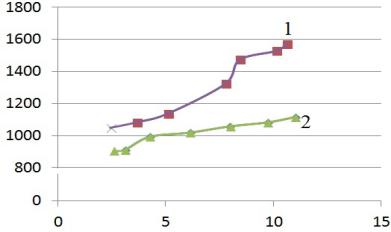
The results of the experiment are in the graph (Fig. 5).
transmissi, |
С) |
Coefficient of heat |
Watt/(m² ° |
Average temperature pressure, ° С
Fig. 5. Graph of the dependence of the heat transmission coefficient on the temperature pressure: 1 of the shell-and-tube heat exchange tool with the changed geometry of the heat exchange surface; 2 of the tool according to the GOST (ГОСТ) 27590-2005
The graph shows that the heat transmission coefficient К, Watt/(m² °С) increases as does the average temperature pressure and is on average 20 % larger than that of the serial heat exchange manufactured according to the GOST (ГОСТ) 27590-2005.
Conclusions. As part of the experimental studies, it was proved that turbulization of the heated liquid in the shell-and-tube tool [13] with the cylindrically shaped rib causes intensification of heat exchange. An increase in the heat transmission coefficient during a seasonal increase in the temperature pressure (the lower is the temperature of the outside air, the higher is the temperature pressure) is more intense in the investigated tool (Fig. 5) than in the serial one (GOST (ГОСТ) 27590-2005). A large heat transfer coefficient К, Watt/(m² °К), ultimately results in a reduction in the standard size of a heat exchange tool.
The operation of a highly effective shell-and-tube tool with the changed geometry of the heat exchange surface is believed to enable one to take advantage of the lamellar tool (high turbulization) as well as to raise the reliability of heat supply systems and simplify as and cut down current and routine maintenance costs.
References
1. Alkhasova D. A. ["Mukhtar's readings": The increase in heat transfer between the flows of ribbing partition].
Trudy "Mukhtarovskie chteniya": Sovremennye problemy matematiki i smezhnye voprosy" [Proc. "Mukhtar Readings": Modern problems of mathematics and related issues"]. Makhachkala, 2008, pp. 31—34.
43

Russian Journal of Building Construction and Architecture
2.Bazhan P. I., Sorokin O. G. Podogrevateli VVPI –– dostoinstva, nedostatki, metodika predvaritel'nogo podbora [Heaters VVPI – advantages, disadvantages, methods of pre-selection]. Novosti teplosnabzheniya, 2006, no. 3, pp. 39––47.
3.Bashmakov I. A. Analiz osnovnykh tendentsii razvitiya sistem teplosnabzheniya Rossii [Analysis of the main trends in the development of heat supply systems in Russia]. Novosti teplosnabzheniya, 2008, no. 90, pp. 51––58.
4.Buglaev V. T., Anisin A. A. Vliyanie geometricheskikh parametrov sferoidal'nykh elementov rel'efa i skhemy ikh raspolozheniya na teplovuyu effektivnost' plastinchatoi poverkhnosti teploobmena [Influence of geometrical parameters of spheroidal relief elements and their arrangement scheme on thermal efficiency of plate heat exchange surface]. Izvestiya vuzov. Yadernaya energetika, 2002, no. 3, pp. 39––49.
5.Zhukauskas A. A. Konvektivnyi perenos v teploobmennikakh [Convective transfer in heat exchangers]. Moscow, Nauka Publ., 1982. 472 p.
6.Kruglov G. A., Bakunin V. V., Andreeva M. V. Teoreticheskie issledovaniya stepeni vzaimosvyazi turbulizatsii potoka s koeffitsientom teplootdachi [Theoretical studies of the degree of relationship between the flow turbulence and the heat transfer coefficient]. Vestnik KrasGASU, 2015, no. 6, pp. 67––73.
7.Kuntysh V. B., Sukhotskii A. B., Yatsevich A. V. Teplovaya effektivnost' vikhrevoi intensifikatsii teplootdachi gazovogo potoka pri prodol'nom i poperechnom obtekanii kruglotrubnykh poverkhnostei [Thermal efficiency of vortex intensification of gas flow heat transfer at longitudinal and transverse flow around round-tube surfaces]. Izvestiya vysshikh uchebnykh zavedenii SNG, 2014, no. 2, pp. 68––75.
8.Kucherenko D. I. Ochistka vodopodogrevatelei sistem goryachego vodosnabzheniya i otopleniya [Cleaning of water heaters of hot water supply and heating systems]. Novosti teplosnabzheniya, 2004, no. 2, pp. 56––60.
9.Kushchev L. A., Nikulin N. Yu., Ovsyannikov Yu. G. [The use of heat exchangers in the systems of housing and communal services of the Belgorod region]. Trudy "Nauchno-tekhnicheskie problemy sovershenstvovaniya i razvitiya sistem gazoenergosnabzheniya" [Proc. "Scientific and technical problems of improvement and development of gas and energy supply systems"]. Saratov, 2018, pp. 111––116.
10.Kushchev L. A., Nikulin N. Yu., Alifanova A. I. Sovremennye metody intensifikatsii teploobmena v kozhukhotrubnykh teploobmennykh apparatakh ZhKKh [Modern methods of heat exchange intensification in shell-and-tube heat exchangers of housing and communal services]. Vestnik BGTU im. V. G. Shukhova, 2017, no. 9, pp. 73––79.
11.Nekrasov A. S., Sinyak Yu. V., Voronina S. A. Perspektivy razvitiya teplosnabzheniya Rossii [Prospects for the development of a heat supply of Russia]. Novosti teplosnabzheniya, 2011, no. 128, pp. 125––131.
12.Olesevich K. A., Olesevich A. K., Osipov M. I. Eksperimental'noe issledovanie teplogidravlicheskikh kharakteristik kozhukhotrubnogo teploobmennogo apparata s vintovoi peregorodkoi [Experimental study of thermohydraulic characteristics of a shell-and-tube heat exchanger with a screw partition]. Vestnik Moskovskogo gosudarstvennogo tekhnicheskogo universiteta im. N. E. Baumana, 2004, no. 2, pp. 262––265.
13.Nikulin N. Yu., Kushchev L. A., Suslov D. Yu. e. a. Kozhukhotrubyi teploobmennyi apparat [Shell and tube heat exchanger]. Patent RF, no. 2014134083/06, 2015. 12 p.
14.Statistika [Statistics]. Ministerstvo energetiki RF: ofitsial. sait. Available at: https://minenergo.gov.ru/activity/statistic.
15.Shlikhting G. Teoriya pogranichnogo sloya [The theory of the boundary layer]. Moscow, Nauka Publ., 1974. 712 p.
44