Материал: Russian Journal of Building Construction and Architecture

Issue № 3 (43), 2019 |
ISSN 2542-0526 |
DOI10.25987/VSTU.2019.3.43.003
UDC 697:620.9(07)
L. А. Kuschev1, N. Yu. Nikulin2, А. Yu. Feoktistov3
HIGHLY EFFICIENT SHELL-AND-TUBE HEAT EXCHANGERS
FOR COMMUNAL HOUSEHOLD SYSTEMS
Belgorod State Technological University Named after V.G. Shukhov1, 2, 3
Russia, Belgorod
1D. Sc. in Engineering, Prof. of the Dept. of Heat and Gas Supply and Ventilation, tel.: (4722)55-94-38, e-mail: Nick_973gt@mail.ru
2PhD student of the Dept. of Heat and Gas Supply and Ventilation, tel.: +7-908-788-8313, e-mail: Nick_973gt@mail.ru
3PhD in Engineering, Assoc. Prof. of the Dept. of Heat and Gas Supply and Ventilation, tel.: (4722)55-94-38, e-mail: Nick_973gt@mail.ru
Statement of the problem. Heat and gas supply equipment (heat networks and boiler rooms) in the Russian Federation is generally worn-out. An important element of the heat and gas supply system is shell-and-tube and lamellar heat exchangers that are employed in thermal electric stations and atomic electric stations, boiler rooms, etc. The use of these tools is a more viable engineering solution than lamellar ones due to a number of operational and economic factors. The methods of enhancing heat exchange of shell-and-tube tools are discussed.
Results and conclusions. It was found that the most promising method of enhancing heat exchange is to change the geometry of a heat exchanger surface: longitudinally ribbed heat exchanger tubes, tubes with a hole on the outside surface, etc. The theoretical aspects of increasing heat emission of the heated solid surface using liquid turbulization. An original structure of the shell- and-tube heat exchanger with special heat exchange tubes fitted with plates with cylindrical ribs. According to the natural experiment, the heat exchange coefficient of the resulting shell-and-tube heat exchanger with the modified geometry of the heat exchanger surface and on average 20 % higher turbulization than that of the mass production one.
Keywords: heat exchanger, turbulization, heat exchanger surface, heat exchange coefficient.
Introduction. The heat supply system of the Russian Federation is the largest in the world
with the heat energy consumption of around 35 % of the total one [3].
The article was prepared as part of the federal development program of the Branch University with the support from the Belgorod State Technological University Named after V.G. Shukhov: N A-35/17 "Intensification of Heat Exchange in Shell-and-Tube Heat Supply Systems of Communal Households" from 24.07.17.
© Kuschev L. А., Nikulin N. Yu., Feoktistov А. Yu., 2019
35
Russian Journal of Building Construction and Architecture
However, these days a heat supply system is faced with technological challenges during production, transfer and distribution of heat energy: the proportion of boiler rooms with completely worn out equipment is around 60 %, the average percentage of worn out thermal and steam networks is estimated at 60––70 %, worn out equipment in heat supply system is reported to be 60 %.
In the Russian Federation the communal household system is one of the most crucial industries in the public sector. Reconstruction as well as construction of new residential homes, energy modernization of the country’s heat supply infrastructure is a top priority in the social policy. The annual proportion of residential construction is about 2 % of the housing fund [11].
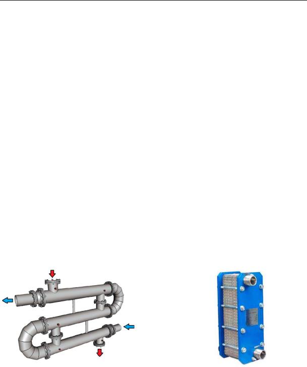
A significant part of the Russian Federation is located in sharply and moderately continental climate zones. The heating season might last from 72 to 365 days. In order to create favourable work and leisure conditions heat supply systems are employed. Currently over 500 large heat energy sources are being employed in the Russian Federation (atomic power plants, thermal electric power plants, boiler rooms with the power capacity of over 58 MWatt) [17]. In the calendar year of 2017 according to the data from the Ministry of Energy, the Russian Federation produced 4,94 108 Gcal of thermal energy, which is 13 % more than in the previous year [14]. The main type of heat exchange equipment for thermal energy production is shell-and-tube and lamellar heat exchange tools (Fig. 1). This equipment is employed in thermal electric power plants and atomic power plants, boiler rooms, central and individual thermal spots.
-
а) |
b) |
Fig. 1. Shell-and-tube (а) and lamellar (b) heat exchange tools
The use of lamellar heat exchangers is associated with operation and maintenance challenges. First of all, heat exchange surfaces experience skulling. A limescale layer with the thickness 0.3 mm causes a 2.5 time decrease in the heat transfer coefficient compared to the calculation data [2, 8]. A scaling inhibitor, i.e. oxyethylidenediphosphonic acid, can be added into a hot water supply system in order to prevent skulling [9].
36
Issue № 3 (43), 2019 |
ISSN 2542-0526 |
Heat exchanger plates should be disassembled or assembled by a team of no less than 2 professionals with use of special equipment. Rubber gaskets (EPDM material) of a complex shape are damaged which require replacement if a tool is frequently (3 or more times) disassembled. The cost of gaskets should be 30––70 % of that of a new tool with actual service life of rubber gaskets of around 3––5 years. Therefore EPDM-compactions have to be replaced 1––2 times after 5 years of operation.
Traditionally in heat supply systems in the Russian Federation shell-and-tube heat exchange tools are more widely used which typically have a relatively low hydraulic resistance and can use operating environments with various aggregate states (steam in the heating contour, water in the heated one and the other way round). These tools can operate on water with extreme rigidity (over 700 mkg-equiv/l), temperature (up to 550°) and high pressure (up to 14 МPа). It should be noted that for shell-and-tube heat exchangers the skulling thickness of 0.3 mm only causes a 10 % reduction in the heat transfer coefficient.
Hence for analysis of the positive and negative aspects of heat exchange tools, intensification of heat exchange in shell-and-tube tools for increasing their productivity is of particular importance.
1. Theoretical foundation of intensification of heat exchange in the geometry of a heat exchange surface. The Russian Federation as well as other countries is engaged in studies of intensification of heat exchange in shell-and-tube heat exchange tools.
Intensification of heat exchange is discussed in the paper by D. A. Alkhasova [1]. The efficiency of the method of longitudinal ribbing of a heat exchange tube was investigated and a 4––5 time increase in the heat flow was achieved compared to a bare surface. However, as the number of longitudinal ribs raises so does the hydraulic resistance.
In [12] there is a discussion of a shell-and-tube heat exchange tool where a block of regular support partitions (perpendicular to the tool axis) was replaced by a screw one. This contributes to a 1.4 time increase in heat exchange compared to a serial tool manufactured in accordance with the GOST (ГОСТ) 24590-2005. It is also essential to account for challenges associated with manufacturing the tool as well as a relatively high hydraulic resistance at high rates of the operating environment in tube space.
In the papers by G. А. Kruglov and V. V. Bakunin [6] it is suggested that a smooth pipe is used which is bent like a spiral to increase heat emission from a heating heat carrier to a wall pipe by 1.5 times.
Specialists in the Belarus State Technological University [7] conducted a series of experimental studies on longitudinal flowing by a heat exchange pipe with notches on the outside
37

Russian Journal of Building Construction and Architecture
surface. This enabled heat exchange to increase by 1.39 times with heat emission dropping dramatically as the notches experienced skulling.
In a lot of countries (USA, Canada, Great Britain, Germany, France, India, China, Iraq) there has been ongoing research effort to investigate the efficiency of shell-and-tube heat exchange tools [18, 19]. Original technical solutions for improving turbulization of a liquid flow at the heated as well as cooled surface (in the heating and heated contour).
Chinese specialists M. Jin, H. Liu, K. Wang performed a study of a shell-and-tube heat exchange tool with smooth pipes and modernized partitions which were a circle with alternating 60° sectors [16]. The sector angle was also 60 °. The goal of the experiment was to investigate a coefficient of heat exchange and hydraulic resistance. According to the results, the heat coefficient using such partitions could be increase by 6,8 % (compared to regular partitions). A drawback of this technical solution is challenging manufacturing of the tool.
In Iran Ashkan Alimoradi developed and examined a shell-and-tube heat exchange tool with spiral heat exchange pipes. A heat exchange pipe was found to emit more heat, the smaller its rolling radius is [20]. Hence the heat exchange coefficient of the tool with a spiral pipe can be increased by 6 %. It should be noted that in this case the area of a longitudinal section of tube space is a lot smaller than with straight pipes, which causes the tool size to increase.
Intensification of heat exchange of heated liquid in shell-and-tube heat exchange tools by means of turbulization is also worth mentioning when the liquid turbulization, which is an advantage of lamellar tools, is suggested being used for structures of shell-and-tube ones due to cost efficiency, simplicity and convenience of their operation and maintenance.
The amount of heat energy that is transmitted from a heated solid body to a liquid of a cooler temperature depends on liquid flowing of the body. According to the calculations by A. A. Zhukauskas [5], in the Reynolds number area (for liquid surfaces) 2 103––104 at the turbulence of the heated liquid flow Tu = 10 % an increase in heat emission is 20––25 %. In the classical papers by А. А. Zhukauskas, G. Shlichting [5, 15] it was found that during flowing of the cylinder liquid with a flow starting from Re = 60, behind the feeding part there is a swirling area. At Re = 5000 and over behind the feeding part there is a liquid flow with a high turbulization.
It should be noted that in a laminar sublayer heat is transmitted from the wall to the liquid (or the other way round) there is heat conductivity. The thicker a laminar sublayer is, the less heat is transmitted to the main flow. Thus a decrease in the thickness of the laminar sublayer of the liquid near the plate contributes to an increase in the heat energy (an increase in the heat emission coefficient) through this layer.
38
Issue № 3 (43), 2019 |
ISSN 2542-0526 |
The heat emission coefficient from the plate to the liquid , Watt/(m² °С) is known to be given by the formula:
|
Nu |
, |
(1) |
|
l |
|
|
where λ is the heat conductivity coefficient of the body, Watt/(m К); Nu is the Nusselt number; l is the defining geometric parameter of the surface (length for the plate, m, its diameter, m, for the cylinder).
The Nusselt number Nu during liquid flowing of the plate is calculated for the turbulent mode using the formula:
Nu |
ж,l |
0.037 Re0.8 |
Pr0.43 |
(Pr |
/Pr |
)0.25, |
(2) |
|
ж,l |
ж,l |
ж,l |
cт |
|
|
where Reж,l is the Reynolds number which goes up as turbulization of a liquid flow takes place; Pr is the Prandtl number.
For the cylinder the number Nu depends on turbulization of the flowing liquid:
Nu |
ж,l |
0.43 Re0.6 |
Pr0.35 |
Tu0.15 |
(Pr |
/Pr |
)0.25, |
(3) |
|
ж,l |
ж,l |
|
ж,l |
cт |
|
|
where Tu is the coefficient of the turbulization of the liquid flowing the cylinder, %.
Based on (3), as the numbers Reж,l, Pr increase as well as does turbulization а [4], the number Nuж,l goes up during liquid flowing of the plate. For the cylinder based on the dependence (4), the number Nu increases as do the number Tu, Re and Pr. Then based on (2), as Nu increases, so does the heat emission coefficient . Hence in order to intensify heat exchange in the shell-and- tube tool, turbulization of a liquid flow in the heat exchange surface should be increased.
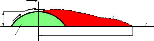
Considering the results in [5, 15], we set forth a scheme of a heat exchange surface (Fig. 2) which consists of a plate and a round semi-cylinder.
|
|
W |
0 |
|
|
|
W |
ж |
W ж |
|
|
|
||
|
|
|
1 |
|
Н |
W |
ж |
|
|
|
2 |
|||
|
|
|||
|
|
|
||
|
3 |
|
L |
|
|
|
|
||
Fig. 2. Development of movement behind a cylindrically shaped rib:
1 is an area of swirling and high turbulization; 2 is a plate; 3 is a cylindrically shaped rib; Wж is a tangential speed during flowing of the cylindrically shaped rib, m/seс;
W0 is the rate of the main liquid flow, m/seс
39