Материал: Russian Journal of Building Construction and Architecture
Russian Journal of Building Construction and Architecture
does the pressure increase at the moment respectively. This is completely in agreement with the criterion of use of maximum light moving parts in structures of shock nodes to reach their maximum efficiency and reliability as specified in [6, p. 67].
A(1,2jΩ)
1
0,8
0,6
0,4
0,2
0
0 |
2 |
|
4m1 |
6 m2 |
8 |
m3 |
10 |
Ω, rad12/sec |
|
|
|||||||||
|
|
|
|
|
|||||
|
|
|
|
|
|
Fig. 9. Amplitude and frequency characteristics of the shock node when the valve closes depending on changes in the mass of its moving parts: т1 < т2 < т3, т2 is the basic parameter
A(1,2jΩ)
1
0,8
0,6
0,4
0,2
0
0 |
2 |
4 |
l1 |
6l2 |
l38 |
10 |
Ω, rad/12sec |
|
|
|
|||||||
Fig. 10. Amplitude and frequency characteristics of the shock node when the valve closes depending on changes in the deformation of its moving parts: l1 < l2 < l3, l2 is the basic parameter
30
Issue № 3 (43), 2019 |
ISSN 2542-0526 |
Fig. 10 suggests that as the deformation (a decrease in the rigidity) of the elements of the shock node increase, its maximum efficiency is reached at lower valve switching frequencies. Conversely, an increase in the rigidity of a structure causes a shift in the effective frequency of the generation of the impulses of the hydraulic shock and increases it.
A1,2(jΩ)
1
0,8
0,6
0,4
0,2
0
0 |
2 |
4 |
|
6 |
8 |
10 |
12 |
|
|
|
|
|
V1 |
V2 |
V3 |
|
Ω, rad/sec |
|
|
|
|
|
|
|||
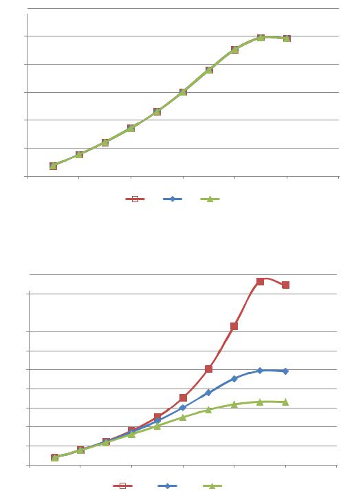
Fig. 11. Amplitude and frequency characteristics of the shock node when the valve closes depending on changes in the consumption of the operating environment: V1 < V2 < V3, V2 is the basic parameter
A(jΩ)2
1,8
1,6
1,4
1,2
1
0,8
0,6
0,4
0,2
0
0 |
2 |
4 |
6 |
8 |
10 |
12 |
|
|
|
|
r2_1 |
r2_2 |
r2_3 |
|
Ω, rad/sec |
|
|
|
|
|
|||
Fig. 12. Amplitude and frequency characteristics of the shock node when the valve closes depending on changes in the mechanical (active) resistance of the valve:: r2_1 < r2_2 < r2_3, r2_2 – are the basic parameters
31

Russian Journal of Building Construction and Architecture
Fig. 11 suggests that changes in the consumption of the operating environment when the other basic parameters of the system are stable have no influence on the choice of an optimal frequency of the generation of hydraulic shocks. For the chosen construction solution for the setup the most effective frequency is within 1.5 Hz. When the valves of the shock node are externally operated, this describes its stable operation as the consumption of the operating environment changes unlike a self-powered structure of the valve where the consumption of the operating environment defines its switching frequency and a relatively small range of the operation frequency [4].
Fig. 12 shows that active mechanical resistance of the valve is directly proportionate to the closing rate change of the valve v, m/seс.
Conclusions. Through the course of the study a technical solution for the shock node of the opposite structure was obtained making it possible to externally operate its valves, which allows the impulses of the amount of movement in the operating environment to be generated with the specified frequency and amplitude independent of its consumption. The novelty of the proposed structure is proved by the Russian Federation patent [8].
The results of the experimental study of the operation of the above shock node with the standard size G3/2 are indicative of its productivity at the valve switching frequency from 0.1 to 2.5 Hz in the range of changes in the consumption of the operating environment 0.176–– 2.241 m3/h (2.94––37.35 l/min). As the consumption drops below that, hydraulic shock is not generated and as the consumption increases, the network pump operates in the emergency mode with an overcurrent as a result of an extreme hydraulic resistance of the shock node. The latter is also accompanied by depressurization of compacting materials and failure of some elements of the structure of the shock node itself and the hydraulic contour as a result of the impact of a powerful hydraulic shock.
The experimentally obtained graphs of pressure changes at the moment of the hydraulic shock allow a maximum pressure growth to be predicted at the moment of the hydraulic shock for a certain hydraulic system. E. g., if the permissible pressure for a heat supply system is 1000 kPа, there should be no increase of over 25 l/min in the consumption of the operating environment through the shock node of a structure with the standard size G3/2 . Besides, for each hydraulic system some maximum increase in the pressure in the impulse of the hydraulic shock depending on the frequency of valve switching should be taken into consideration.
The results of the mathematical modeling show that all the parameters of the energy chain except active hydraulic resistance of the valve and consumption of the operating environment have a significant influence on the character of the generation of the hydraulic shock by
32
Issue № 3 (43), 2019 |
ISSN 2542-0526 |
means of the shock node. An increase in the mass of the moving parts causes a decrease in the maximum amplitude and frequency characteristics and its shift to a lower angular speed. An increase in the deformation (a decrease in the rigidity of the reverse valve spring) also causes a shift in the maximum amplitude and frequency characteristics into lower frequencies but with no changes in the amplitude. What is typical of mechanical systems is that as active mechanical resistance of the valve drops, there is a sharp increase in the amplitude.
Therefore it can be stated that the suggested structure of the operated shock node allows the impulses of the amount of movement of the operating environment to be generated with a necessary frequency and amplitude of a pressure increase at the moment of a hydraulic shock in a relatively wide range of changes in the consumption of the operating environment. Hence the resulting technical solution can be applied for extending the potential of impulse and pulsing circulation of a heat carrier in the context of intensifying heat exchange, transformation of available head pressure from one hydraulic contour into another and self-purification of heat-transmitting surfaces in heat supply systems of the above values and quantitative indices obtained using self-powered shock nodes. The detailed data will be presented in the follow-up papers.
References
1.Galitseiskii B. M., Ryzhov Yu. A., Yakush E. V. Teplovye i gidrodinamicheskie protsessy v koleblyushchikhsya potokakh [Thermal and hydrodynamic processes in oscillating flows]. Moscow, Mashinostroenie Publ., 1977. 256 p.
2.Levtsev A. P., Makeev A. N. Impul'snye sistemy teplo- i vodosnabzheniya [Impulse systems of heat and water supply]. Saransk, Izd-vo Mordov. un-ta, 2015. 172 p.
3.Makeev A. N. Impul'snaya sistema teplosnabzheniya obshchestvennogo zdaniya. Avtoref. diss. kand. tekhn. nauk [Impulse heat supply system of public building. Dr. eng. sci. diss.]. Penza, 2010. 20 p.
4.Makeev A. N. Issledovanie kharakteristik udarnogo uzla samopodderzhivayushcheisya oppozitnoi konstruktsii [Study of the characteristics of the impact unit of self-supporting opposition structure]. Promyshlennaya energetika, 2018, no. 3, pp. 32––37.
5.Makeev A. N. K voprosu lokal'noi organizatsii impul'sno-koleblyushcheisya tsirkulyatsii teplonositelya v sisteme teplosnabzheniya [To the question of local organization of pulse-oscillating circulation of coolant in the heat supply system]. Byulleten' nauki i praktiki. Nizhnevartovsk, 2018, vol. 4, no. 5, pp. 254––262.
6.Ovsepyan V. M. Gidravlicheskii taran i tarannye ustanovki [The hydraulic RAM and RAM setup]. Moscow, Mashinostroenie Publ., 1968. 124 p.
7.Levtsev A. P., Makeev A. N., Makeev S. N., Khramov S. I., Narvatov Ya. A. Teplovoi punkt [Heat point]. Patent RF, no. 2013137717/12, 2015.
8.Levtsev A. P., Makeev A. N., Golyanin A. A. Udarnyi uzel [Shock node]. Patent RF, no. 2018112914, 2018.
33

Russian Journal of Building Construction and Architecture
9.Levtsev A. P., Makeev A. N., Lazarev A. A. Avtonomnaya sistema otopleniya dlya zdaniya avtonomnogo pol'zovaniya [Autonomousheating systemfor thebuilding of Autonomoususe].PatentRF,no.2009113871/22,2009.
10.Rostovtsev V. N. Utylyzacija malыhъ padenij vodы dlja celej osushenija y oroshenija zemel' [Disposal of small drops of water for drainage and irrigation purposes]. Petrograd, 1916. 48 p.
11.Akcay S., Akdag U. Parametric investigation of effect on heat transfer of pulsating flow of nanofluids in a tube using circular rings. Amukkale university journal of engineering sciences-pamukkale universitesi muhendislik bilimleri dergisi, 2018, vol. 24, iss. 4, pp. 597––604. doi: 10.5505/pajes.2017.70120.
12.Ali S., Habchi Ch., Menanteau S., Lemenand T., Harion J.-L. Heat transfer and mixing enhancement by free
elastic flaps oscillation. International Journal of Heat and Mass Transfer, 2015, vol. 85, pp. 250––264. doi: 10.1016/j.ijheatmasstransfer.2015.01.122.
13.Butun H., Kantor I., Marechal F. A heat integration method with multiple heat exchange interfaces. ENERGY: 30th International Conference on Efficiency, Cost, Optimisation, Simulation and Environmental Impact of Energy Systems (ECOS), 2018, vol. 152, pp. 476––488. doi: 10.1016/j.energy.2018.03.114; WOS: 000432760200042.
14.Chang S. W., Su L. M., Hwang C. C., Yang T. L. Heat transfer in a reciprocating duct fitted with transverse ribs. Experimental heat transfer, 1999, vol. 12, iss. 2, pp. 95––115. doi: 10.1080/089161599269735.
15.Désidéri J.-A., Duvigneau R. Parametric optimization of pulsating jets in unsteady flow by multiple-gradient descent algorithm (MGDA). Computational Methods in Applied Sciences, 2019, vol. 47, pp. 151––169. doi: 10.1007/978-3-319-78325-3_11.
16.Dushin N. S., Mikheev N. I., Paereliy A. A., Gazizov I. M., Shakirov R. R. Kinematics of pulsating flow in the entry region of the channel with discrete roughness elements. Journal of Physics: Conference Series, 2017, vol. 891, iss. 1. doi: 10.1088/1742-6596/891/1/012147.
17.Kærn M. R., Elmegaard B., Meyer K. E., Palm B., Holst J. Continuous versus pulsating flow boiling. Experimental comparison, visualization, and statistical analysis. Science and Technology for the Built Environment, 2017, vol. 23, iss. 6, pp. 983––996. doi: 10.1080/23744731.2017.1319667.
18.Levtzev A. P., Makeev A. N., Kudashev S. F. Pulsating heat transfer enhancement in the liquid cooling system of power semiconductor converter. Indian Journal of Science and Technology, 2016, vol. 9 (11). doi: 10.17485/ijst/2016/v9i11/89420.
19.Makeev А. N. Implementation of pulse heat supply for dependent connection of customers = Obespechenie impul'snogo teplosnabzheniya dlya zavisimogo prisoedineniya abonentov. Magazine of Civil Engineering = Inzhenerno-stroitel'nyi zhurnal, 2018, no. 07 (83), pp. 114––125. doi: 10.18720/MCE.83.11.
20.Makeev А. N. Theory of pulse circulation of the heater in the heat supply system with independent subscription of subscribers. Russian journal of building construction and architecture, 2018, no. 4 (40), pp. 15––25. wos: 000450361700002.
21.Seo Y. K., Byung H. K., Jae M. H. Heat transfer in the thermally developing region of a pulsating chan-
nel flow. International Journal of Heat and Mass Transfer, 1993, vol. 36, iss. 17, pp. 4257––4266. doi: 10.1016/0017-9310(93)90088-N.
22.Sundstrom L. R. J., Cervantes M. J. On the Similarity of Pulsating and Accelerating Turbulent Pipe Flows. Flow turbulence and combustion, 2018, vol. 100, iss. 2, pp. 417––436. doi: 10.1007/s10494-017-9855-5.
23.Valueva E. P., Purdin M. S. Heat exchange at laminar flow in rectangular channels. Thermophysics and aeromechanics, 2016, vol. 23, iss. 6, pp. 857––867. doi: 10.1134/S0869864316060081.
34