Материал: Стандарт MIL-STD-202G
MIL-STD-202G
FIGURE 211-1. Test condition A.
FIGURE 211-2. Test condition B.
FIGURE 211-3. Test condition C.
METHOD 211A
14 April 1969
5
MIL-STD-202G
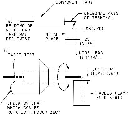
STEP 1. Bend lead with fingers, over rounded edge of metal plate as shown in (a). STEP 2. Center component part in chuck; secure lead in clamp as shown in (b).
STEP 3. Rotate chuck part through 360° at a rate of approximately 5 seconds per 360° rotation. Successive rotations shall be in alternate directions. A total of three such 360° rotations shall be performed. During this test, the chuck shall rotate around an axis which is fixed with respect to the padded clamp, or vice versa. The chuck shall have no appreciable end play during rotation.
NOTE: Metric equivalents are in parentheses.
FIGURE 211-4. Test condition D.
METHOD 211A
14 April 1969
6
MIL-STD-202G
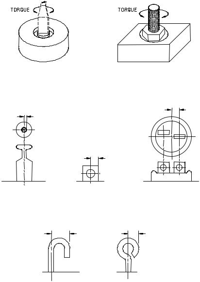
FIGURE 211-5. Test condition E.
NOTE: Equivalent diameter is twice the distance between the lines indicated by the arrows.
FIGURE 211-6. Method of determining equivalent diameter.
METHOD 211A
14 April 1969
7
MIL-STD-202G
METHOD 212A
ACCELERATION
1.PURPOSE. This test is performed for the purpose of determining the effects of acceleration stress on component parts, and to verify the ability of the component parts to operate properly during exposure to acceleration stress such as would be experienced in aircraft, missiles, etc.
2.APPARATUS. Unless otherwise specified, the acceleration test apparatus shall be the centrifuge-type and shall be capable of subjecting the test specimen to the value of acceleration (g’s) as specified in 3. The acceleration gradient across the specimen shall not exceed 15 percent of the specified g level.
2.1 Mounting accessories. Provisions shall be made to permit mounting by the normal means so that the specimen can be tested in both directions, 180 degrees apart, of each of three mutually perpendicular axes, unless otherwise specified. Parts with axial terminations weighing less than 0.5 ounce shall be soldered to stand-off terminals, leaving a distance of 0.2 inch to 0.3 inch from the point of emergence to the terminals. Parts weighing 0.5 ounce and more shall be clamped so as to avoid any stress on the leads. Parts having radial leads and those of unusual mass distribution shall be mounted as specified in the individual specification. If loading, actuating, or polarizing currents are required, they shall be specified. Provisions shall be made for all electrical connections to be secure.
3. PROCEDURE. The specimen under test shall be mounted in a rigid position as specified in 2.1 and shall be subjected to one of the following test conditions, as specified in the individual specification:
3.1Test condition A. The specimen shall be subjected to 5 minutes acceleration of the specified "g" level in both directions of each of three mutually perpendicular axes for a total of 30 minutes at either 20, 50, or 100g level. The acceleration measured at any point of the component part shall not exceed 15 percent of the "g" level.
3.2Test condition B. The specimen shall be subjected for 1 minute at nominally 10,000 or 20,000g in the direction as specified in the individual specification. The rate of acceleration shall be increased smoothly from zero to the specified value in not less than 20 seconds. The rate of acceleration shall be decreased smoothly to zero in not less than 20 seconds.
3.3Test condition C. The specimen shall be subjected to the value of acceleration specified in the individual specification for 10 minutes in both directions of each of three mutually perpendicular axes. The acceleration shall be increased smoothly from zero to the specified value in approximately 2 minutes. The acceleration shall be decreased smoothly to zero in not less than 2 minutes.
4. MEASUREMENTS. The measurements made before, during, or after the test shall be as specified.
METHOD 212A 18 April 1973
1 of 2