|
DICOM PS3.3 2020a - Information Object Definitions |
Page 391 |
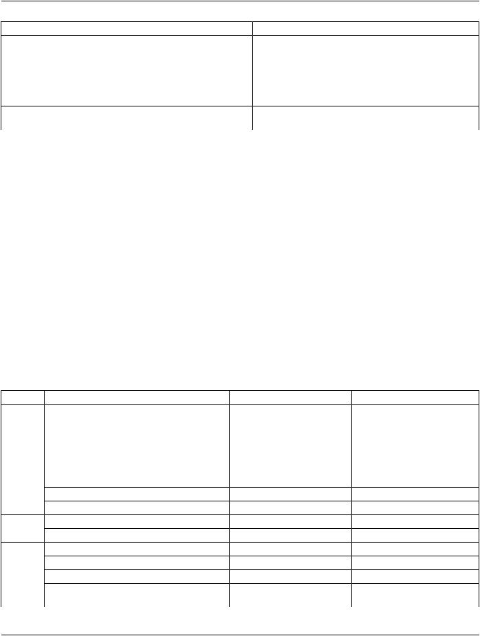
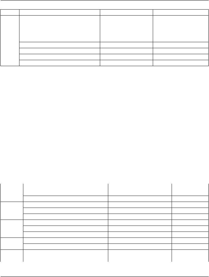
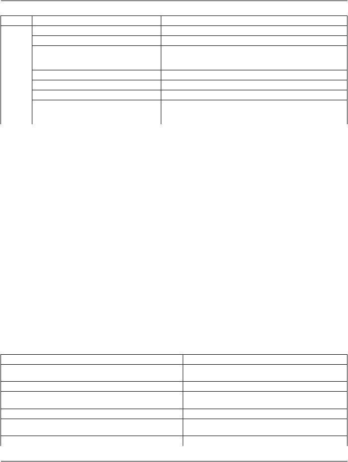
IE |
Module |
Reference |
Usage |
|
|
Intravascular OCT Image |
C.8.27.2 |
M |
|
|
Intravascular OCT Acquisition Parameters |
C.8.27.3 |
M |
|
|
Intravascular OCT Processing Parameters |
C.8.27.4 |
C - Required if Presentation Intent |
|
|
|
Type (0008,0068) is FOR |
|
|
|
|
PROCESSING. |
|
|
Intravascular Image Acquisition Parameters |
C.8.27.5 |
M |
|
|
SOP Common |
C.12.1 |
M |
|
|
Common Instance Reference |
C.12.2 |
M |
|
|
Frame Extraction |
C.12.3 |
C - Required if the SOP Instance was |
|
|
|
created in response to a Frame-Level |
|
|
|
retrieve request |
|
A.66.3.1 Intravascular Optical Coherence TomographyImage IOD Content Constraints
The following constraints on Image Attributes take precedence over the descriptions given in the Module Attribute Tables.
A.66.3.1.1 Contrast/Bolus Agent Sequence
For Contrast/Bolus Agent Sequence (0018,0012), the Defined Context Group is 3850.
A.66.3.1.2 Prohibited Modules
The Overlay Plane Module and VOI LUT Module shall not be used in a Standard Extended SOP Class of the Intravascular Optical Coherence Tomography Image.
Note
In order to annotate images, whether during acquisition or subsequently, SOP Instances of the Grayscale Softcopy Presentation State Storage or the Structured Report Storage SOP Classes that reference the image SOP Instance may be used.
Pseudo-color presentation information may be applied through the use of separate Pseudo-color Softcopy Presentation State SOP instances.
NostandardmechanismisprovidedforinclusionofannotationswithintheimageSOPInstanceitselfandimplementersarediscouraged from using private extensions to circumvent this restriction.
A.66.4 Intravascular Optical Coherence Tomography Image Functional Group Macros
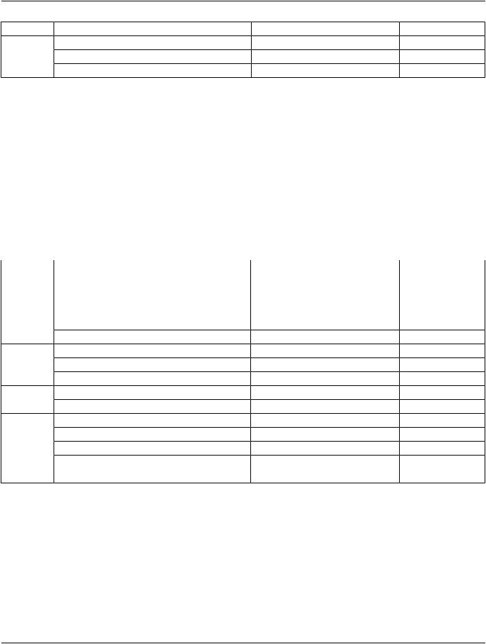
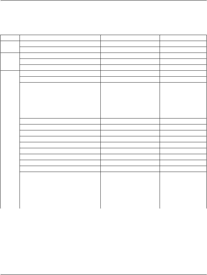
TableA.66.4.3-1 specifiesthe useofthe FunctionalGroup Macrosused inthe Multi-frameFunctional GroupsModule for theIntravas- cular Optical Coherence Tomography Image IOD.
Table A.66.4.3-1. Intravascular Optical Coherence Tomography Image Functional Group Macros
Functional Group Macro |
Section |
Usage |
Pixel Measures |
C.7.6.16.2.1 |
C - Required if Presentation Intent Type (0008,0068) is FOR |
|
|
PRESENTATION. |
Frame Content |
C.7.6.16.2.2 |
M - May not be used as a Shared Functional Group. |
Derivation Image |
C.7.6.16.2.6 |
C - Required if the image or frame has been derived from |
|
|
another SOP Instance. |
Frame Anatomy |
C.7.6.16.2.8 |
M |
Cardiac Synchronization |
C.7.6.16.2.7 |
C-RequiredifCardiacSynchronizationTechnique(0018,9037) |
|
|
equals other than NONE May be present otherwise. |
Frame VOI LUT |
C.7.6.16.2.10 |
U |