Материал: part03

Внимание! Если размещение файла нарушает Ваши авторские права, то обязательно сообщите нам

Page 376​

DICOM PS3.3 2020a - Information Object Definitions​

The Acquisition Context information may be entered during acquisition, or obtained from the Modality Worklist using information​ supplied in the Protocol Context, using TID 15101 “NM/PET Protocol Context”.​

A.57 Surface Segmentation IOD​

A.57.1 Surface Segmentation IOD Description​

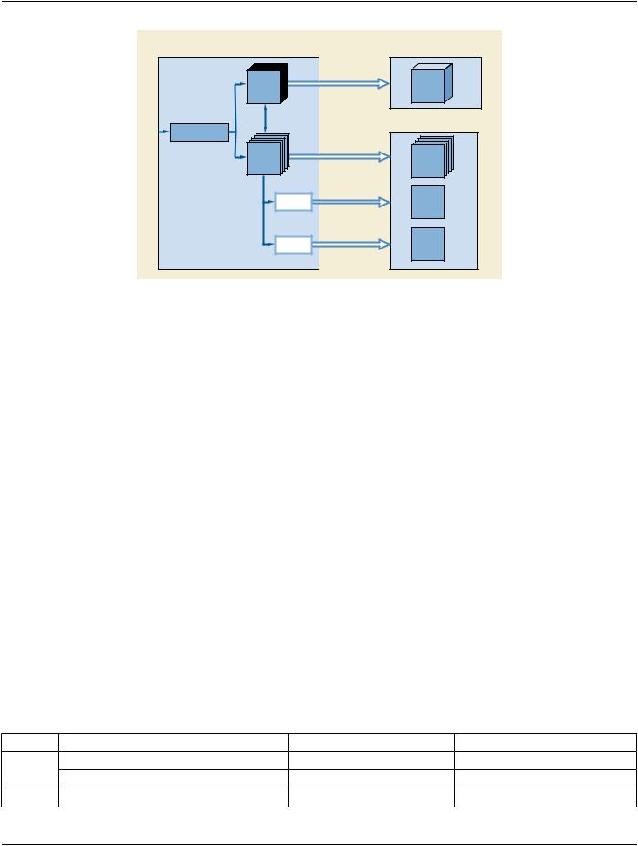
The Surface Segmentation Information Object Definition (IOD) specifies a polygonal representation of a three dimensional surface.​ A Surface Segmentation SOP Instance may reference an externally defined coordinate system via the Frame of Reference UID​ (0020,0052) or establish its own coordinate system.​

The Surface Segmentation IOD does not include the full set of acquisition parameters of the referenced images, e.g., cardiac phase.​ An application rendering or processing the segmentation may need to access the referenced images for such information.​

One Segmented Surface Instance can contain one or more surfaces. Each surface within a Segmented Surface IE is represented as​ a single object.​

A.57.2 Surface Segmentation IOD Entity-Relationship Model​

This IOD uses the E-R Model in Section A.1.2, with only the Surface IE below the Series IE.​

A.57.3 Surface Segmentation IOD Module Table​

Table A.57-1 specifies the Modules of the Surface Segmentation IOD.​

Table A.57-1. Surface Segmentation IOD Modules​

IE​

Module​

Reference​

Usage​

Patient​

Patient​

C.7.1.1​

M​


Clinical Trial Subject​

C.7.1.3​

U​

Study​

General Study​

C.7.2.1​

M​


Patient Study​

C.7.2.2​

U​


Clinical Trial Study​

C.7.2.3​

U​

Series​

General Series​

C.7.3.1​

M​


Segmentation Series​

C.8.20.1​

M​


Clinical Trial Series​

C.7.3.2​

U​

Frame of​

Frame of Reference​

C.7.4.1​

M​

Reference​


Equipment​

General Equipment​

C.7.5.1​

M​


Enhanced General Equipment​

C.7.5.2​

M​

Surface​

Surface Segmentation​

C.8.23.1​

M​


Surface Mesh​

C.27.1​

M​


Common Instance Reference​

C.12.2​

C-Requiredifthesurfacehas​


been derived from another​


SOP Instance​


General Reference​

C.12.4​

U​


SOP Common​

C.12.1​

M​

A.57.4 Surface Segmentation IOD Content Constraints​

The Defined CID for Purpose of Reference Code Sequence (0040,A170) within Source Instance Sequence (0042,0013) in the Gen-​ eral Reference Module shall be CID 7019 “Segmentation Non-Image Source Purposes of Reference”.​

- Standard -​

DICOM PS3.3 2020a - Information Object Definitions​

Page 377​

A.58 Color Palette IOD​

A.58.1 Color Palette IOD Description​

A Color Palette entity specifies a color palette suitable for application to a grayscale image or parametric map.​

A.58.2 Color Palette IOD Entity-Relationship Model​

AColorPaletteisnotrelatedtootherInformationEntitiesoftheDICOMreal-worldmodel,asitisnotassociatedwithaspecificPatient.​ The E-R model for the Color Palette IOD is shown in Figure A.58.2-1.​

Color

Palette

IOD

Figure A.58.2-1. Color Palette IOD E-R Model​

A.58.3 Color Palette IOD Module Table​

Table A.58.3-1 lists the Modules that make up the Color Palette IOD.​

Table A.58.3-1. Color Palette IOD Modules​

IE​

Module​

Reference​

Usage​

Color Palette​SOP Common​

C.12.1​

M​


Color Palette Definition​

C.28.1​

M​


Palette Color Lookup Table​

C.7.9​

M​


ICC Profile​

C.11.15​

M​

Note​

The number of bits for each entry in the Lookup Table Data is constrained in the Palette Color Lookup Table Module to be​ 8 in this IOD.​

A.59 Enhanced US Volume IOD​

A.59.1 Enhanced US Volume IOD Description​

Image objects of different types may be created from a 3D Ultrasound image acquisition, illustrated in Figure A.59-1. It can be seen​ that there are two different types of data related to 3D image acquisition: 3D volume data and several kinds of 2D image derived from​ the volume data.​

- Standard -​

Page 378​

DICOM PS3.3 2020a - Information Object Definitions​


Enhanced US SOP Classes


Ultrasound Modality

3D Volume type

Cartesian

Volume

Scan Line

Processed Data

2D Frames

Volume

Slicing

Volume

Rendering

Export of

Volume Data

3D Volume

Data

US SOP Classes 2D Image types

Export of Direct

Viewing Frames Spatially-

related

2D Frames

Export of

MPR Views MPR

View

Export of

Volume-Rendered

Views Rendered

View

Figure A.59-1. Types of 3D Ultrasound Source and Derived Images (Informative)​

The 3D volume data (the diagonally shaded box in Figure A.59-1) contains a Cartesian volume or two or more temporally related​ Cartesian volumes. 3D volume data is exchanged using the Enhanced US Volume SOP Class, and are suitable for subsequent Multi-​ Planar Reconstruction and rendering operations. Within each Enhanced US Volume instance, each Cartesian volume consists of a​ set of parallel planes, and each plane consists of one or more frames each of a single data type. All Cartesian volumes have the​ same spacing between adjacent planes.​

Most acquisition devices construct the Cartesian volume by resampling data from a different acquisition geometry. The method of​ generation of the Cartesian volume, its relationship to spatially-related 2D frames (whether the volume was created from spatially-​ relatedframes,orspatially-relatedframesextractedfromtheCartesianvolume),andthealgorithmsusedforMulti-PlanarReconstruction​ and rendering operations are outside the scope of this Standard.​

The 2D image types represent collections of frames that are derived from the volume data, namely 3D rendered views (projections),​ separate Multi-Planar Reconstructed (MPR) views, or collections of spatially-related source frames, either parallel or oblique (the​ cross-hatched boxes in Figure A.59-1). The Ultrasound Image and Ultrasound Multi-frame Image IODs are used to represent these​ derived images. See Section A.6 for the Ultrasound Image IOD description or Section A.7 for the Ultrasound Multi-frame Image IOD​ description.​

Note​

See Annex PP “3D Ultrasound Volumes (Informative)” in PS3.17 for an informative discussion on the use of these objects​ for the exchange of 3D ultrasound volume data.​

A.59.2 Enhanced US Volume IOD Entity-Relationship Model​

This IOD uses the E-R Model in Section A.1.2, with only the Image IE below the Series IE.​

A.59.3 Enhanced US Volume IOD Module Table​

Table A.59-1 specifies the Modules of the Enhanced US Volume IOD.​

Table A.59-1. Enhanced US Volume IOD Modules​

IE​

Module​

Reference​

Usage​

Patient​

Patient​

C.7.1.1​

M​


Clinical Trial Subject​

C.7.1.3​

U​

Study​

General Study​

C.7.2.1​

M​

- Standard -​


DICOM PS3.3 2020a - Information Object Definitions​

Page 379​

IE​

Module​

Reference​

Usage​


Patient Study​

C.7.2.2​

U​


Clinical Trial Study​

C.7.2.3​

U​


Series​

General Series​

C.7.3.1​

M​


Enhanced US Series​

C.8.24.1​

M​


Clinical Trial Series​

C.7.3.2​

U​


Frame of​ Frame of Reference​

C.7.4.1​

M​


Reference​Ultrasound Frame of Reference​

C.8.24.2​

M​


Synchronization​

C.7.4.2​

M​


Equipment​General Equipment​

C.7.5.1​

M​


Enhanced General Equipment​

C.7.5.2​

M​


Image​

General Image​

C.7.6.1​

M​


General Reference​

C.12.4​

U​


Image Pixel​

C.7.6.3​

M​


Enhanced Contrast/Bolus​

C.7.6.4b​

C - Required if contrast media was​


applied. See Section A.59.3.1.2 for​


baseline context group ID.​


Multi-frame Functional Groups​

C.7.6.16​

M​


Multi-frame Dimension​

C.7.6.17​

M​


Cardiac Synchronization​

C.7.6.18.1​

C - Required if cardiac​


synchronization was applied.​


Respiratory Synchronization​

C.7.6.18.2​

C - Required if respiratory​


synchronization was applied.​


Device​

C.7.6.12​

U​


Acquisition Context​

C.7.6.14​

M​


Specimen​

C.7.6.22​

U​


Enhanced Palette Color Lookup Table​

C.7.6.23​

U​


Enhanced US Image​

C.8.24.3​

M​


IVUS Image​

C.8.24.4​

C - Required if Modality = IVUS​


Excluded Intervals​

C.8.24.5​

U​


ICC Profile​

C.11.15​

U​


SOP Common​

C.12.1​

M​


Common Instance Reference​

C.12.2​

U​


Frame Extraction​

C.12.3​

C - Required if the SOP Instance was​


createdinresponsetoaFrame-Level​


retrieve request​


A.59.3.1 Enhanced US Volume IOD Content Constraints​

A.59.3.1.1 Associated Physiological Waveforms​

The Acquisition Time Synchronized (0018,1800) Attribute shall have a value of 'Y' if associated physiological waveforms are linked​ to the Enhanced US Volume. As described in the Synchronization Module, the same value of Synchronization Frame of Reference​ UID (0020,0200) is shared between the Waveform and Enhanced US instances to indicate a common temporal Frame of Reference​ for Acquisition DateTime (0008,002A) values in the waveform and Enhanced US instances. Further, Frame Reference DateTime​ (0018,9151) may be used in optimizing alignment between the displayed image and displayed physiological waveforms.​

- Standard -​

Page 380​

DICOM PS3.3 2020a - Information Object Definitions​

In the case of gated acquisition in which information from multiple events (such as ECG beats) are used to create sub-volumes that​ are "spliced" or "interleaved" together to form the volume data, the Excluded Intervals Module describes the timing of each of the​ constituent sub-volumes for correlation with the physio waveform.​

Note​

It is recommended that the Waveform Annotation Module in the General ECG Waveform IOD be used to indicate the times​ oftheR-waveeventswithintheacquisitionduration.ThisallowstheviewingapplicationtobeabletomarkthoseR-Rintervals​ that contributed to the acquisition of the Enhanced US Volume.​

A.59.3.1.2 Contrast​

Baseline CID for the Contrast/Bolus Agent Sequence (0018,0012) in the Enhanced Contrast/Bolus Module is CID 12030 “Ultrasound​ Contrast/Bolus Agents”.​

A.59.4 Enhanced US Volume Functional Group Macros​

Table A.59-2 specifies the use of the Functional Group Macros used in the Multi-frame Functional Groups Module for the Enhanced​ US Volume IOD.​

Table A.59-2. Enhanced US Volume Functional Group Macros​

Functional Group Macro​

Section​

Usage​

Frame Content​

C.7.6.16.2.2​

M - May not be used as a Shared Functional Group.​

Pixel Measures​

C.7.6.16.2.1​

M​

Plane Position (Patient)​

C.7.6.16.2.3​

C - Required if Ultrasound Acquisition Geometry​


(0020,9307) has a value of PATIENT. May be present​


otherwise. See Section A.59.4.1.2.​

Plane Orientation (Patient)​

C.7.6.16.2.4​

C - Required if Ultrasound Acquisition Geometry​


(0020,9307) has a value of PATIENT. May be present​


otherwise. See Section A.59.4.1.2.​

Referenced Image​

C.7.6.16.2.5​

U​

Derivation Image​

C.7.6.16.2.6​

C - Required if the image or frame has been derived from​


another SOP Instance.​

Cardiac Synchronization​

C.7.6.16.2.7​

C - Required if Cardiac Synchronization is used​

Frame VOI LUT​

C.7.6.16.2.10​

M​

Real World Value Mapping​

C.7.6.16.2.11​

U​

Contrast/Bolus Usage​

C.7.6.16.2.12​

C - Required if the Enhanced Contrast/Bolus Module is​


present.​

Patient Orientation in Frame​

C.7.6.16.2.15​

U​

Frame Display Shutter​

C.7.6.16.2.16​

U​

Respiratory Synchronization​

C.7.6.16.2.17​

C - Required if Respiratory Synchronization is used​

Plane Position (Volume)​

C.7.6.16.2.21​

M - May not be used as a Shared Functional Group. See​


Section A.59.4.1.2.​

Plane Orientation (Volume)​

C.7.6.16.2.22​

M - May not be used as a Per-Frame Functional Group.​


See Section A.59.4.1.2.​

Temporal Position​

C.7.6.16.2.23​

C - Required if frames are temporally related and not​


temporally referenced to a Cardiac or Respiratory event​

Image Data Type​

C.7.6.16.2.24​

M​

US Image Description​

C.8.24.6.1​

M - May not be used as a Per-Frame Functional Group​

- Standard -​