Материал: part03

Внимание! Если размещение файла нарушает Ваши авторские права, то обязательно сообщите нам

Page 366​

DICOM PS3.3 2020a - Information Object Definitions​

A.52.4 Ophthalmic Tomography Image IOD Content Constraints​

The following constraints on Image Attributes take precedence over the descriptions given in the Module Attribute Tables.​

A.52.4.1 Contrast/Bolus Agent Sequence​

For Contrast/Bolus Agent Sequence (0018,0012), the Defined Context Group is 4200.​

A.52.4.2 Overlay Plane Module and VOI LUT Module​

TheOverlayPlaneModule and VOILUT Moduleshallnot beused in a StandardExtended SOPClass of the Ophthalmic Tomography​

Image.​

Note​

In order to annotate images, whether during acquisition or subsequently, SOP Instances of the Grayscale Softcopy​ Presentation State Storage or the Structured Report Storage SOP Classes that reference the image SOP Instance may be​ used.​

Pseudo-color presentation information may be applied through the use of separate Pseudo-color Softcopy Presentation State SOP​ instances.​

NostandardmechanismisprovidedforinclusionofannotationswithintheimageSOPInstanceitselfandimplementersarediscouraged​ from using private extensions to circumvent this restriction.​

A.52.4.3 Ophthalmic Tomography Image Functional Group Macros​

TableA.52.4.3-1specifiestheuseoftheFunctionalGroupMacrosusedintheMulti-frameFunctionalGroupsModulefortheOphthalmic​

Tomography Image IOD.​

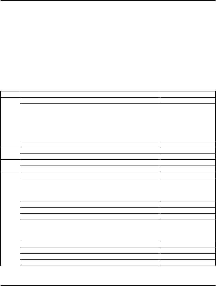
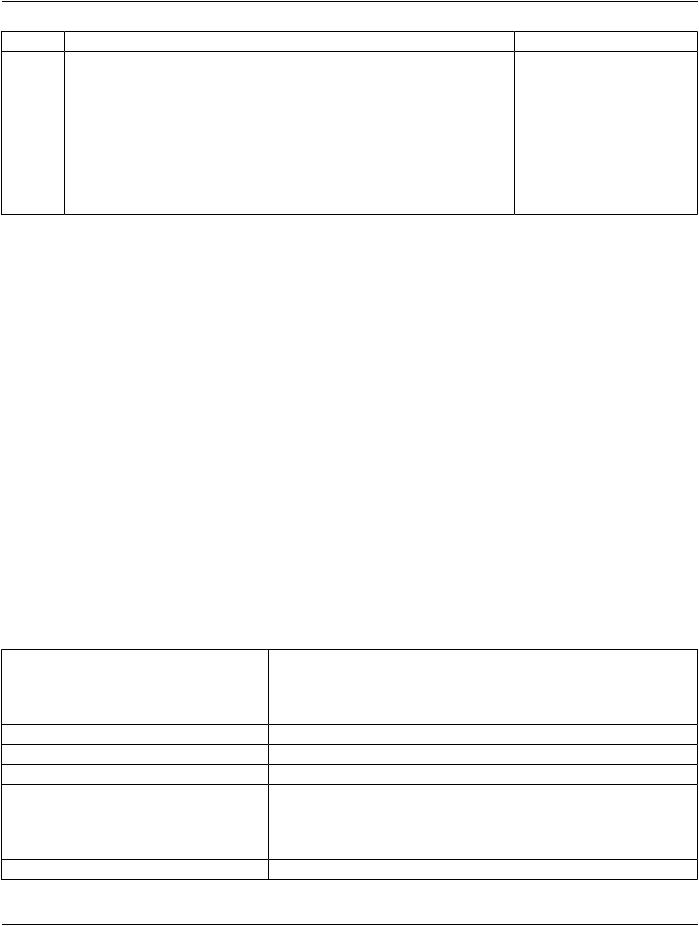
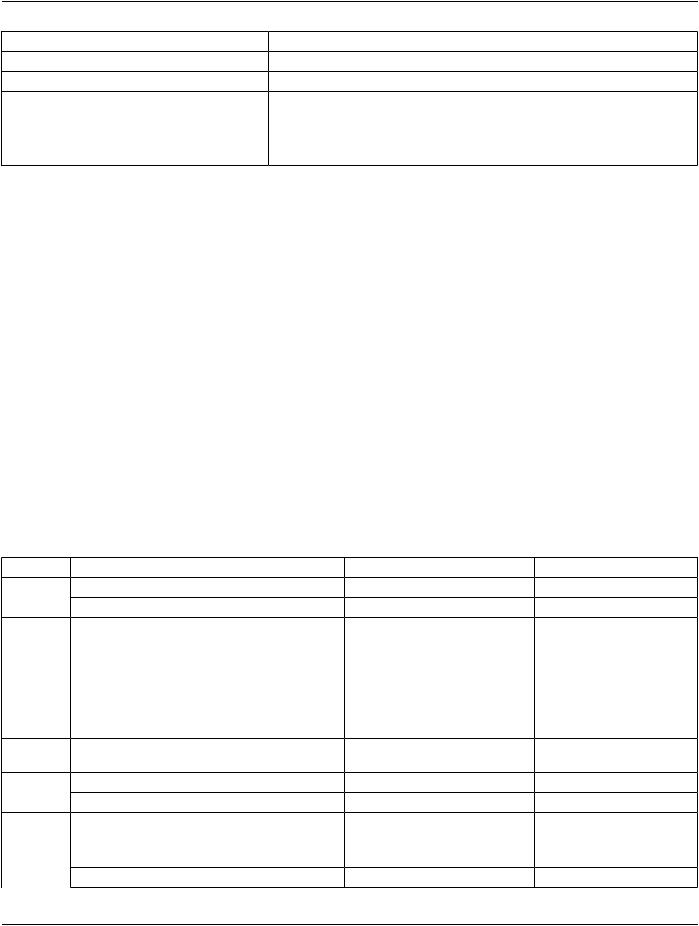
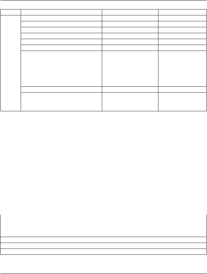
Table A.52.4.3-1. Ophthalmic Tomography Functional Group Macros​

Functional Group Macro​

Section​

Usage​

Pixel Measures​

C.7.6.16.2.1​

M​

Frame Content​

C.7.6.16.2.2​

M - May not be used as a Shared Functional Group.​

Plane Position (Patient)​

C.7.6.16.2.3​

C - Required if no Ophthalmic Photography Reference Image is​


availableorifOphthalmicVolumetricPropertiesFlag(0022,1622)​


is YES; May be present otherwise​

Plane Orientation (Patient)​

C.7.6.16.2.4​

C - Required if no Ophthalmic Photography Reference Image is​


availableorifOphthalmicVolumetricPropertiesFlag(0022,1622)​


is YES; May be present otherwise​

Referenced Image​

C.7.6.16.2.5​

C - Required if Ophthalmic Photography Reference Image is​


available.​

Derivation Image​

C.7.6.16.2.6​

C - Required if the image or frame has been derived from another​


SOP Instance.​

Frame Anatomy​

C.7.6.16.2.8​

M​

Cardiac Synchronization​

C.7.6.16.2.7​

C - Required if Cardiac Synchronization Technique (0018,9037)​


equals other than NONE. May be present otherwise.​

Contrast/Bolus Usage​

C.7.6.16.2.12​

C - Required if Contrast/Bolus Agent Sequence (0018,0012) is​


used. May not be used as a Shared Functional Group​

Ophthalmic Frame Location​

C.8.17.10.1​

U​

- Standard -​

DICOM PS3.3 2020a - Information Object Definitions​

Page 367​

A.53 X-Ray 3D Angiographic Image IOD​

A.53.1 X-Ray 3D Angiographic Image IOD Description​

This Section defines the Information Object for multi-dimensional reconstructed cone beam X-Ray Angiographic Images and includes​ those Attributes and Information Objects necessary for the interchange of Multi-dimensional X-Ray volumes.​

Examples of X-Ray 3D Angiographic Images are: 3D reconstruction of static vascular structures (e.g., in Neuro-Radiology), ECG​ triggered cardiac volumes at different phases in the cardiac cycle, coronary artery tree reconstructions.​

A.53.2 X-Ray 3D Angiographic Image IOD Entity-Relationship Model​

This IOD uses the E-R Model in Section A.1.2, with only the Image IE below the Series IE.​

A.53.3 X-Ray 3D Angiographic Image IOD Image Module Table​

Table A.53-1. X-Ray 3D Angiographic Image IOD Modules​

IE​

Module​

Reference​

Usage​

Patient​

Patient​

C.7.1.1​

M​


Clinical Trial Subject​

C.7.1.3​

U​

Study​

General Study​

C.7.2.1​

M​


Patient Study​

C.7.2.2​

U​


Clinical Trial Study​

C.7.2.3​

U​

Series​

General Series​

C.7.3.1​

M​


Clinical Trial Series​

C.7.3.2​

U​


Enhanced Series​

C.7.3.3​

M​

Frame of​ Frame of Reference​

C.7.4.1​

M​

Reference​Synchronization​

C.7.4.2​

U​

Equipment​General Equipment​

C.7.5.1​

M​


Enhanced General Equipment​

C.7.5.2​

M​

Image​

Image Pixel​

C.7.6.3​

M​


Enhanced Contrast/Bolus​

C.7.6.4b​

C-Requiredifcontrastmediawas​


applied.​


Device​

C.7.6.12​

U​


Intervention​

C.7.6.13​

U​


Acquisition Context​

C.7.6.14​

M​


Multi-frame Functional Groups​

C.7.6.16​

M​


Multi-frame Dimension​

C.7.6.17​

U​


Cardiac Synchronization​

C.7.6.18.1​

C - Required if cardiac​


synchronization was applied.​


Respiratory Synchronization​

C.7.6.18.2​

C - Required if respiratory​


synchronization was applied.​


Patient Orientation​

C.7.6.20​

U​


Image - Equipment Coordinate Relationship​

C.7.6.21​

U​


Specimen​

C.7.6.22​

U​


X-Ray 3D Image​

C.8.21.1​

M​

- Standard -​

Page 368​


DICOM PS3.3 2020a - Information Object Definitions​


IE​


Module​

Reference​

Usage​


X-Ray 3D

Angiographic Image Contributing​

C.8.21.2.1​

U​


Sources​


X-Ray 3D

Angiographic Acquisition​

C.8.21.3.2​

U​


X-Ray 3D

Reconstruction​

C.8.21.4​

U​


SOP Common​

C.12.1​

M​


Common Instance Reference​

C.12.2​

U​


Frame Extraction​

C.12.3​

C - Required if the SOP Instance​


was created in response to a​


Frame-Level retrieve request​

A.53.3.1 X-Ray 3D Angiographic Image IOD Content Constraints​

A.53.3.1.1 Modality Attribute​

Modality (0008,0060) shall have the value XA.​

A.53.3.1.2 Restrictions for Standard Extended SOP Classes​

The Overlay Plane Module, VOI LUT Module and Softcopy Presentation LUT Module shall not be used in a Standard Extended SOP​ Class of the X-Ray 3D Angiographic Image.​

Note​

1.​The VOI LUT function is provided by a Frame VOI LUT Functional Group.​

2.​The Curve Module (Retired) was previously included in the Image IE for this IOD but has been retired. See PS3.3-2004.​

A.53.3.1.3 Image - Equipment Coordinate Relationship Module​

For X-Ray 3D Angiographic Images created from SOP Instances of the Enhanced XA SOP Class (1.2.840.10008.5.1.4.1.1.12.1.1)​ the isocenter coordinate system is used to describe the positioning of the table and positioner (see Section C.8.19.6.13), and shall​ use only the Defined Term ISOCENTER for Equipment Coordinate System Identification (0028,9537).​

A.53.4 X-Ray 3D Angiographic Image Functional Group Macros​

Table A.53-2 specifies the use of the Functional Group Macros used in the Multi-frame Functional Groups Module for the X-Ray 3D​ Angiographic Image IOD.​

Table A.53-2. X-Ray 3D Angiographic Image Functional Group Macros​

Functional Group Macro​

Section​

Usage​

Pixel Measures​

C.7.6.16.2.1​

M​

Frame Content​

C.7.6.16.2.2​

M - May not be used as a Shared​


Functional Group.​

Plane Position (Patient)​

C.7.6.16.2.3​

M​

Plane Orientation (Patient)​

C.7.6.16.2.4​

M​

Referenced Image​

C.7.6.16.2.5​

U​

Derivation Image​

C.7.6.16.2.6​

C - Required if Image Type (0008,0008)​


Value 1 equals DERIVED.​

Cardiac Synchronization​

C.7.6.16.2.7​

U​

Frame Anatomy​

C.7.6.16.2.8​

M​

Pixel Value Transformation​

C.7.6.16.2.9​

U​

- Standard -​

DICOM PS3.3 2020a - Information Object Definitions​

Page 369​

Functional Group Macro​

Section​


Usage​

Frame VOI LUT​

C.7.6.16.2.10​

M​


Real World Value Mapping​

C.7.6.16.2.11​

U​


Contrast/Bolus Usage​

C.7.6.16.2.12​

C - Required if the Enhanced​


Contrast/Bolus Module is present.​

Respiratory Synchronization​

C.7.6.16.2.17​

U​


X-Ray 3D Frame Type​

C.8.21.5.1​

M​


A.53.4.1 X-Ray 3D Angiographic Image Functional Group Macros Content Constraints​

A.53.4.1.1 Frame Anatomy Functional Group Macro​

The Defined CID for the Anatomic Region Sequence (0008,2218) shall be CID 4042 “XA/XRF Anatomy Imaged”.​

A.54 X-Ray 3D Craniofacial Image IOD​

A.54.1 X-Ray 3D Craniofacial Image IOD Description​

This Section defines the Information Object for multi-dimensional reconstructed cone beam X-Ray Craniofacial Images and includes​ those Attributes and Information Objects necessary for the interchange of Multi-dimensional X-Ray volumes.​

ExamplesofX-Ray3DCraniofacialImagesare:3Dreconstructionofcraniofacialstructuresforsurgicalplacementofimplants,dimen-​ sional analysis for orthodontic therapy and evaluation of craniofacial pathology.​

A.54.2 X-Ray 3D Craniofacial Image IOD Entity-Relationship Model​

This IOD uses the E-R Model in Section A.1.2, with only the Image IE below the Series IE.​

A.54.3 X-Ray 3D Craniofacial Image IOD Module Table​

Table A.54-1 specifies the Modules of the X-Ray 3D Craniofacial Image IOD.​

Table A.54-1. X-Ray 3D Craniofacial Image IOD Modules​

IE​

Module​

Reference​

Usage​

Patient​

Patient​

C.7.1.1​

M​


Clinical Trial Subject​

C.7.1.3​

U​

Study​

General Study​

C.7.2.1​

M​


Patient Study​

C.7.2.2​

U​


Clinical Trial Study​

C.7.2.3​

U​

Series​

General Series​

C.7.3.1​

M​


Clinical Trial Series​

C.7.3.2​

U​


Enhanced Series​

C.7.3.3​

M​

Frame of​

Frame of Reference​

C.7.4.1​

M​

Reference​


Equipment​General Equipment​

C.7.5.1​

M​


Enhanced General Equipment​

C.7.5.2​

M​

Image​

Image Pixel​

C.7.6.3​

M​


Enhanced Contrast/Bolus​

C.7.6.4b​

C - Required if contrast media​


was applied.​


Device​

C.7.6.12​

U​

- Standard -​

Page 370​

DICOM PS3.3 2020a - Information Object Definitions​


IE​

Module​

Reference​

Usage​


Intervention​

C.7.6.13​

U​


Acquisition Context​

C.7.6.14​

M​


Multi-frame Functional Groups​

C.7.6.16​

M​


Multi-frame Dimension​

C.7.6.17​

U​


Patient Orientation​

C.7.6.20​

U​


Image - Equipment Coordinate Relationship​

C.7.6.21​

U​


Specimen​

C.7.6.22​

U​


X-Ray 3D Image​

C.8.21.1​

M​


X-Ray 3D Craniofacial Image Contributing Sources​C.8.21.2.2​

U​


X-Ray 3D Craniofacial Acquisition​

C.8.21.3.3​

U​


X-Ray 3D Reconstruction​

C.8.21.4​

U​


SOP Common​

C.12.1​

M​


Common Instance Reference​

C.12.2​

U​


Frame Extraction​

C.12.3​

C - Required if the SOP​


Instance was created in​

response to a Frame-Level​ retrieve request​

A.54.3.1 X-Ray 3D Craniofacial Image IOD Content Constraints​

A.54.3.1.1 Modality Attribute​

Modality (0008,0060) shall have the value DX.​

A.54.3.1.2 Restrictions for Standard Extended SOP Classes​

The Overlay Plane Module, VOI LUT Module and Softcopy Presentation LUT Module shall not be used in a Standard Extended SOP​ Class of the X-Ray 3D Craniofacial Image.​

Note​

1.​The VOI LUT function is provided by a Frame VOI LUT Functional Group.​

2.​The Curve Module (Retired) was previously included in the Image IE for this IOD but has been retired. See PS3.3-2004.​

A.54.4 X-Ray 3D Craniofacial Image Functional Group Macros​

Table A.54-2 specifies the use of the Functional Group Macros used in the Multi-frame Functional Groups Module for the X-Ray 3D​ Craniofacial Image IOD.​

Table A.54-2. X-Ray 3D Craniofacial Image Functional Group Macros​

Functional Group Macro​

Section​

Usage​

Pixel Measures​

C.7.6.16.2.1​

M​

Frame Content​

C.7.6.16.2.2​

M- May not be used as a Shared​


Functional Group.​

Plane Position (Patient)​

C.7.6.16.2.3​

M​

Plane Orientation (Patient)​

C.7.6.16.2.4​

M​

Referenced Image​

C.7.6.16.2.5​

U​

- Standard -​