Материал: part03

Внимание! Если размещение файла нарушает Ваши авторские права, то обязательно сообщите нам

Page 1656​

DICOM PS3.3 2020a - Information Object Definitions​

Attribute Name​

Tag​

Type​

Attribute Description​

>Source Roll Angle​

(300A,067A)​

1C​

Source roll angle in degrees of the Radiation Source at the Control​


Point with respect to the Equipment Coordinate System. The angle​


is a Continuous Rotation Angle, see Section C.36.1.1.5.​


See Section C.36.15.1.1 and Section C.36.12.1.1.​


Required if the conditions in Section C.36.2.2.5.1.1 are satisfied.​

>RT Beam Limiting Device​

(300A,0679)​

1C​

Angle in degrees of the Base Beam Modifier Coordinate System​

Angle​


about the z-axis relative to the parent coordinate system. The angle​


is a Continuous Rotation Angle, see Section C.36.1.1.5.​


See Section C.36.15.1.2.​


Required if the conditions in Section C.36.2.2.5.1.1 are satisfied.​

>Source to Patient Surface​

(300A,0634)​

2C​

Distance in mm from the nominal Radiation Source location to the​

Distance​


Patient surface (skin) along the central beam axis from the source.​


Required if the conditions in Section C.36.2.2.5.1.1 are satisfied.​

>SourcetoExternalContour​

(300A,0132)​

2C​

Distance in mm along thecentral beam axisfrom the nominal​

Distance​


Radiation Source location to the external contour including devices​

associatedwiththepatientanatomymodel.Fordosimetricpurposes​ this value may differ from the Source to Patient Surface Distance​ (300A,0634).​

See Section C.36.11.1.4.​

Required if the conditions in Section C.36.2.2.5.1.1 are satisfied.​

C.36.15.1 C-Arm Photon-Electron Beam Attribute Description​

C.36.15.1.1 Source Roll Angle​

For an Equipment Frame of Reference UID (300A,0675) of 1.2.840.10008.1.4.3.1 (IEC 61217 Fixed Coordinate System Frame of​ Reference), the source roll angle is the rotation of the [IEC 61217] GANTRY coordinate system about the Y-axis of the [IEC 61217]​ FIXED coordinate system.​

C.36.15.1.2 RT Beam Limiting Device Angle​

For an Equipment Frame of Reference UID (300A,0675) of 1.2.840.10008.1.4.3.1 (IEC 61217 Fixed Coordinate System Frame of​ Reference), the RT Beam Limiting Device Angle (300A,0679) is the rotation of the Base Beam Modifier Coordinate System about the​ Z-axis of the [IEC 61217] GANTRY coordinate system.​

C.36.16 Tomotherapeutic Delivery Device Module​

The Tomotherapeutic Delivery Device Module contains tomotherapy-specific information pertaining to the physical device. These​ parameters are used to specify or record the treatment, including geometrical parameters of the collimation system.​

Table C.36.16-1. Tomotherapeutic Delivery Device Module Attributes​

Attribute Name​

Tag​

Type​

Description​

Radiation Source-Axis​

(300A,0640)​

1​

Distance in mm from the nominal Radiation Source location to​

Distance​


the gantry rotation axis.​

- Standard -​


DICOM PS3.3 2020a - Information Object Definitions​

Page 1657​

Attribute Name​

Tag​

Type​

Description​


Include Table C.36.2.2.7-1 “Radiation Generation Mode Macro​

Defined CID for Radiation Type Code Sequence (300A,067F)​

Attributes”.​


is CID 9525 “Radiation Therapy Particle”.​


Defined CID for Energy Unit Code Sequence (300A,0684) is​


CID 9521 “Radiotherapy Treatment Energy Unit”.​


Defined CID for Radiation Fluence Modifier Code Sequence​


(300A,0683) is CID 9549 “Radiation Generation Mode Types”.​

Include Table C.36.2.2.8-1 “RT Beam Limiting Devices Definition​

Defined CID for Device Type Code Sequence (3010,002E)​

Macro Attributes”.​


within 'RT Accessory Device Identification Macro' is CID 9541​


“Beam Limiting Device Types”.​


C.36.17 Tomotherapeutic Beam Module​

The Tomotherapeutic Beam Module specifies or records how a tomotherapeutic treatment is to be or was delivered.​

Table C.36.17-1. Tomotherapeutic Beam Module Attributes​

Attribute Name​

Tag​

Type​

Description​

Table Speed​

(0018,9309)​

1C​

Nominal table speed in mm/s.​


Required if RT Record Flag (300A,0639) equals NO. May be present​


otherwise.​

Revolution Time​

(0018,9305)​

1C​

Nominal time in seconds of one rotation of the gantry.​


Required if RT Treatment Technique Code Sequence (3010,0080)​


contains (130108, DCM, "Helical Beam") and if RT Record Flag​


(300A,0639) equals NO.​


MaybepresentifRTTreatmentTechniqueCodeSequence(3010,0080)​


contains (130108, DCM, "Helical Beam") and if RT Record Flag​


(300A,0639) equals YES.​

Number of RT Control​

(300A,0604)​

1​

Number of RT Control Points in the Tomotherapeutic Control Point​

Points​


Sequence (3010,0098).​


The value shall be equal to or greater than 2.​

Tomotherapeutic Control​

(3010,0098)​

1​

Control Points for the beam delivery.​

Point Sequence​


The number of Items included in this Sequence shall equal the value of​


Number of RT Control Points (300A,0604).​

>Include Table C.36.2.2.6-1 “External Beam Control Point​Defined CID 9558 "Tomotherapeutic Dose Rate Units"​

General Macro Attributes”.​


>Include Table C.36.2.2.9-1 “RT Beam Limiting Device Opening Macro Attributes”.​

>Referenced Radiation​

(300A,0605)​

1C​

The value of Radiation Generation Mode Index (300A,0601) in the​

Generation Mode Index​


Radiation Generation Mode Sequence (300A,067B) in this IOD that​


defines the Radiation Generation Mode used for this Control Point.​


Required if Number of Radiation Generation Modes (300A,0685) is​


present and the conditions in Section C.36.2.2.5.1.1 are satisfied.​

>Source Roll Angle​

(300A,067A)​

1C​

Source roll angle in degrees of the Radiation Source at the Control Point​


with respect to the Equipment Coordinate System. The angle is a​


Continuous Rotation Angle, see Section C.36.1.1.5.​

See Section C.36.15.1.1 and Section C.36.12.1.1.​

Required if the conditions in Section C.36.2.2.5.1.1 are satisfied.​

- Standard -​

Page 1658​

DICOM PS3.3 2020a - Information Object Definitions​

Attribute Name​

Tag​

Type​

Description​

>Tomotherapeutic Leaf​

(3010,0099)​

1C​

The time in seconds each leaf is open during the Control Point interval,​

Open Durations​


see Section C.36.17.1.​


The number of leaves (N) is equal to Number of Parallel RT Beam​


Delimiters (300A,0648).​


N values shall be provided in the order of Parallel RT Beam Delimiter​


Boundaries (300A,0649).​


Required if RT Record Flag (300A,0639) equals NO and the conditions​


in Section C.36.2.2.5.1.1 are satisfied.​

>Tomotherapeutic Leaf​

(3010,009A)​

1C​

The time in seconds each leaf is closed at the beginning of the Control​

Initial Closed Durations​


Point interval, see Section C.36.17.1.​

The number of leaves (N) is equal to Number of Parallel RT Beam​

Delimiters (300A,0648).​

TheNvaluesshallbeprovidedintheorderofParallelRTBeamDelimiter​

Boundaries (300A,0649).​

Required if RT Record Flag (300A,0639) equals NO and at least one​ leafopentimeisnotsymmetricalaboutthemid-pointoftheControlPoint​ interval and the conditions in Section C.36.2.2.5.1.1 are satisfied.​

C.36.17.1 Tomotherapeutic Leaf Closed and Open Durations​

Typically, the Tomotherapeutic Leaf Open Durations (3010,0099) are symmetric about the mid-point of the Control Point interval. If​ they are not, Tomotherapeutic Leaf Initial Closed Durations (3010,009A) is present, which specifies the duration of time that each​ leaf is closed starting from this Control Point. Tomotherapeutic Leaf Open Durations (3010,0099) then specifies the duration of time​ that each leaf is open after Tomotherapeutic Leaf Initial Closed Durations (3010,009A).​

Foreachleaf,thesumoftheTomotherapeuticLeafInitialClosedDurations(3010,009A)andtheTomotherapeuticLeafOpenDurations​ (3010,0099) shall not exceed the Control Point interval.​

Figure C.36.17-1. Diagram of Tomotherapeutic Leaf Open and Closed Durations​

- Standard -​

DICOM PS3.3 2020a - Information Object Definitions​ Page 1659​

Table C.36.17-2. Tomotherapeutic Leaf Open and Closed Durations​

N Control Point​

Attribute​

Leaf 1​

Leaf 2​

Leaf 3​

Index​


1​

Tomotherapeutic Leaf Open Durations​

0.4s​

0.3s​

0.1s​


Tomotherapeutic Leaf Closed Durations​

0​

0​

0.1s​

2​

Tomotherapeutic Leaf Open Durations​

0.5s​

0.3s​

0.1s​


Tomotherapeutic Leaf Closed Durations​


Not present​


3​

Tomotherapeutic Leaf Open Durations​

0.3s​

0.1s​

0​


Tomotherapeutic Leaf Closed Durations​


Not present​


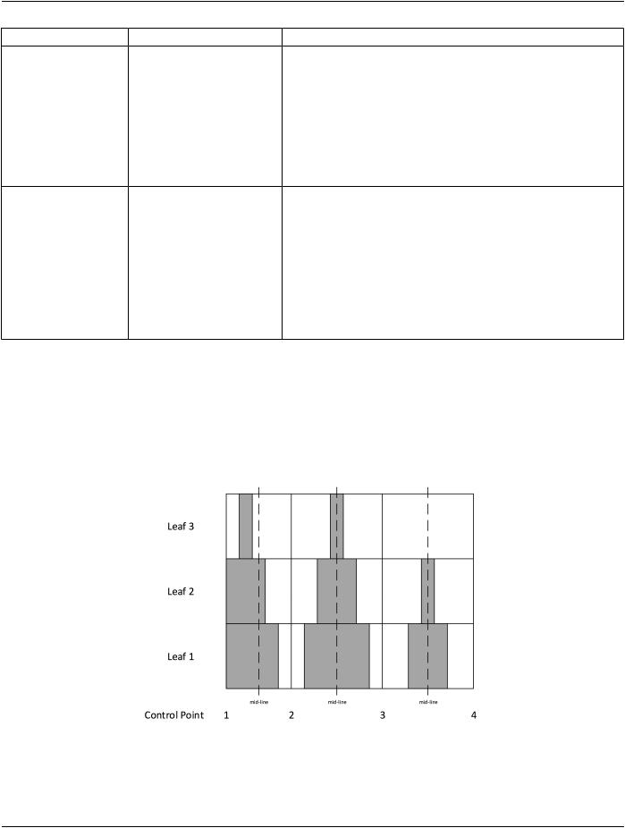
In Figure C.36.17-1, the grey sections indicate when the leaves are open during radiation delivery. Table C.36.17-2 illustrates the​ use of Tomotherapeutic Leaf Open Durations (3010,0099) and Tomotherapeutic Leaf Initial Closed Durations (3010,009A) based on​ the diagram. In the Control Point interval between Control Point 1 and 2, the leaf openings are not symmetric within the Control Point​ interval, so Tomotherapeutic Leaf Initial Closed Durations (3010,009A) is provided.​

In the Control Point interval between Control Point 2 and 3, all leaf opening durations are symmetric about the mid-point of the Control​ Point interval, therefore only Tomotherapeutic Leaf Open Durations (3010,0099) is provided.​

C.36.18 Robotic-Arm Delivery Device Module​

The Robotic-Arm Delivery Device Module contains robot-specific information pertaining to the physical device. These parameters are​ used to specify or record the treatment, including geometric parameters of the collimation system.​

Table C.36.18-1. Robotic-Arm Delivery Device Module Attributes​

Attribute Name​

Tag​

Type​

Description​

Robotic Base Location​

(3010,0090)​

1​

Informative manufacturer-specific description of the location of the​

Indicator​


base of the robot. The value is independent of the Equipment​


Coordinate System.​


Defined Terms:​


FLOOR_LEFT​ Looking from the table towards the robot, the​


robot is floor-mounted to the viewer's left.​


FLOOR_RIGHT​Looking from the table towards the robot, the​


robot is floor-mounted to the viewer's right.​


FLOOR_CENTER​Looking from the table towards the robot, the​


robot is floor-mounted straight ahead of the​


viewer.​

Include Table C.36.2.2.7-1 “Radiation Generation Mode Macro​DefinedCIDforRadiationTypeCodeSequence(300A,067F)isCID​ Attributes”.​ 9525 “Radiation Therapy Particle”.​

Defined CID for Energy Unit Code Sequence (300A,0684) is CID​ 9521 “Radiotherapy Treatment Energy Unit”.​

Defined CID for Radiation Fluence Modifier Code Sequence​ (300A,0683) is CID 9549 “Radiation Generation Mode Types”.​

IncludeTableC.36.2.2.8-1“RTBeamLimitingDevicesDefinition​Defined CID for Device Type Code Sequence (3010,002E) within​ Macro Attributes”.​ 'RT Accessory Device Identification Macro' is CID 9541 “Beam​

Limiting Device Types”.​ Include Table C.36.2.2.14-1 “RT Accessory Holders Definition Macro Attributes”.​

- Standard -​

Page 1660​

DICOM PS3.3 2020a - Information Object Definitions​

C.36.19 Robotic-Arm Path Module​

The Robotic-Arm Path Module specifies or records how a Robotic Path treatment is to be delivered. Multiple paths are encoded as​ separate RT Radiation instances referred to in the RT Radiation Set IOD.​

Table C.36.19-1. Robotic-Arm Path Module Attributes​

Attribute Name​

Tag​

Type​

Description​

RoboticPathNodeSetCode​

(3010,0091)​

1C​

Node Set from which the Robotic Nodes referenced in the Robotic​

Sequence​


Path Control Point Sequence (3010,0097) were selected.​


Only a single Item shall be included in this Sequence.​


Required if RT Record Flag (300A,0639) is NO. May be present​


otherwise.​

>Include Table 8.8-1 “Code Sequence Macro Attributes”.​

DCID 9556 “Radiotherapy Robotic Node Sets”.​

NumberofRTControlPoints​

(300A,0604)​

1​

Number of RT Control Points in the Robotic Path Control Point​


Sequence (3010,0097).​


The value shall be greater than or equal to 2.​

Robotic Path Control Point​

(3010,0097)​

1​

Control Points for the radiation delivery.​

Sequence​


The number of Items included in this Sequence shall equal the value​


of Number of RT Control Points (300A,0604).​

>Include Table C.36.2.2.6-1 “External Beam Control Point​

DCID 9560 “Robotic Delivery Device Dose Rate Units”.​

General Macro Attributes”.​


>Referenced Radiation​

(300A,0605)​

1C​

The value of Radiation Generation Mode Index (300A,0601) in the​

Generation Mode Index​


Radiation Generation Mode Sequence (300A,067B) in this IOD that​


defines the Radiation Generation Mode used for this Control Point.​


Required if Number of Radiation Generation Modes (300A,0685) is​


present and the conditions in Section C.36.2.2.5.1.1 are satisfied.​

>Robotic Node Identifier​

(3010,0092)​

1C​

Identifier of the individual Robotic Node (point in space) along the​


Robotic Path.​


See Note 1.​


Required if the conditions in Section C.36.2.2.5.1.1 are satisfied.​

>RT Treatment Source​

(3010,0093)​

1C​

Coordinates(x,y,z)inmmoftheRadiationSourceCoordinateSystem​

Coordinates​


origin inthe Equipment Coordinate System.​


Required if RT Record Flag (300A,0639) is NO and the conditions in​


Section C.36.2.2.5.1.1 are satisfied.​


May be present if RT Record Flag (300A,0639) is YES and the​


conditions in Section C.36.2.2.5.1.1 are satisfied.​


See Section C.36.12.2.2.​

>Radiation Source​

(3010,0094)​

1C​

RotationangleindegreesoftheRadiationSourceCoordinateSystem​

Coordinate System Yaw​


about the z-axis of the Equipment Coordinate System, see​

Angle​


Section C.36.12.2.2.​

Required if RT Record Flag (300A,0639) is NO and the conditions in​

Section C.36.2.2.5.1.1 are satisfied.​

May be present if RT Record Flag (300A,0639) is YES and the​ conditions in Section C.36.2.2.5.1.1 are satisfied.​

- Standard -​