Материал: part03

Внимание! Если размещение файла нарушает Ваши авторские права, то обязательно сообщите нам


DICOM PS3.3 2020a - Information Object Definitions​

Page 1651​

Attribute Name​

Tag​

Type​

Attribute Description​


Equipment Frame of Reference​

(300A,0675)​

1​

Frame of Reference identifier for the Treatment Delivery​

UID​


Device.​


See Section C.36.12.1.1.​


Equipment Frame of Reference​

(300A,0676)​

3​

Description of Equipment Coordinate System identified​

Description​


bytheEquipmentFrameofReferenceUID(300A,0675).​


See Section C.36.12.1.2.​


Equipment Reference Point​

(300A,0677)​

2​

Coordinates of device-specific reference points.​

Coordinates Sequence​


Zero or more Items shall be included in this Sequence.​


>3D Point Coordinate​

(0068,6590)​

1​

Coordinates(x,y,z)inmmofthedevice-specificreference​


point in the Equipment Coordinate System.​

>Equipment Reference Point​

(300A,0678)​

1​

Identifies the type of reference point.​


Code Sequence​


Only a single Item shall be included in this Sequence.​


>>Include Table 8.8-1 “Code Sequence Macro Attributes”.​


DCID 9554 “Equipment Reference Points”.​


Include Table C.36.2.2.2-1 “RT Patient Support Devices Macro Attributes”.​


C.36.12.1 RT Delivery Device Common Module Attribute Descriptions​

C.36.12.1.1 Equipment Frame of Reference UID​

The Equipment Frame of Reference UID (300A,0675) identifies the Equipment Coordinate System for a Treatment Delivery Device,​ see Section 10.39.1.1.​

The RT Radiation SOP Classes are bound by the Standard to specific Well-known Frames of Reference as defined in Table A-2 in​ PS3.6. For C-Arm based devices delivering radiation at a single machine isocenter this may be the [IEC 61217] coordinate system.​ Devices are calibrated to a specific Well-known Frame of Reference and thus use the corresponding Well-known UID in Equipment​ Frame of Reference UID (300A,0675).​

For RT Radiation SOP Classes the result of the transformation between the Patient-based Coordinate System and the Equipment​ Coordinate System is used to describe the intended treatment position. If two or more transformation matrices describe the relation​ between two or more Patient-based coordinate systems and a single Equipment Coordinate System, any calculations assuming​ transitivityviatheEquipmentCoordinateSystemmustbeperformedwithgreatcarebecausethepatientsanatomymayhavechanged.​

For RT Radiation Record SOP Classes the result of the transformation between the Patient-based Coordinate System and the​ Equipment Coordinate System is used to describe the actual treatment position. In this case the transformation matrices between​ different Patient-Based coordinate Systems and a single Equipment Coordinate System shall not be considered transitive from an​ anatomical point of view and may only be used to compare different treatment positions with respect to the treatment delivery device.​

C.36.12.1.2 Equipment Frame of Reference Description​

The Equipment Frame of Reference Description (300A,0676) is informal and shall not be used for any normative description of the​ Equipment Coordinate System.​

C.36.12.2 Well-known Frame of Reference For Equipment​

The following sections contain specifications of Well-known Frames of Reference used as the Equipment Frame of Reference.​

C.36.12.2.1 IEC 61217 Fixed Reference System Frame of Reference​

The Well-known Value of 1.2.840.10008.1.4.3.1 for Equipment Frame of Reference UID (300A,0675) defines the IEC 61217 Fixed​ Coordinate System Frame of Reference as follows:​

•​The Equipment Coordinate System is the [IEC 61217] FIXED coordinate system.​

- Standard -​

Page 1652​

DICOM PS3.3 2020a - Information Object Definitions​

•​The Base Beam Modifier Coordinate System for all beam modifiers is the [IEC 61217] GANTRY coordinate system. However, RT​ Radiation SOP Classes allow each Beam Modifier Coordinate System to rotate independently from the Base Beam Modifier Co-​ ordinate System.​

Note​

1.​[IEC 61217] refers to the X-axis, Y-axis and Z-axis of the various coordinate systems. When referenced in this Standard​ the capital X/Y/Z is preserved which is not otherwise a DICOM convention.​

2.​FortheC-armPhoton-ElectronRadiationIODandtheTomotherapeuticRadiationIOD,theRTBeamModifier Definition​ Distance (300A,0688) is the same as the Radiation Source-Axis Distance (300A,0640).​

C.36.12.2.2 Standard Robotic-Arm Coordinate System Frame of Reference​

The Well-known Value of 1.2.840.10008.1.4.3.2 for Equipment Frame of Reference UID (300A,0675) identifies the Standard Robotic-​ Arm Coordinate System Frame of Reference to which each device is calibrated during installation.​

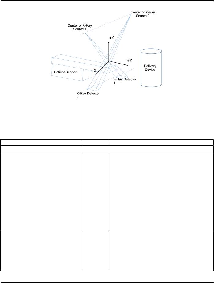
This coordinate system definition requires that two X-Ray detectors are present at the same height and the X-ray beams intersect.​

The right-handed coordinate system axes are oriented as follows, when viewed from the patient support device pedestal towards the​ delivery device:​

•​the x-axis is increasing to the right, parallel to the line between the centers of the X-ray detectors and perpendicular to gravity​

•​the z-axis is increasing away from the direction of gravity​

•​the y-axis is the cross-product of the z- and x-axis​

The origin of the coordinate system is the intersection of the central beams from each X-ray source, where the central beam is the​ line from the X-ray source to the center of the corresponding detector. The coordinate system definition is independent of the location​ of the delivery device and the patient support system.​

MovementsoftherobotheadaredescribedintheStandardRobotic-ArmCoordinateSystem.Therotationoftherobotheadisexpressed​ by a rotation of the Radiation Source Coordinate System with respect to the Standard Robotic-Arm Coordinate System. The origin​ of the Radiation Source Coordinate System is defined at the RT Device Distance Reference Location. The axes of the Radiation​ Source Coordinate System coincide with the Standard Robotic-Arm Coordinate System under the following conditions:​

•​the source position equals 0,0,0, and​

•​the pitch, roll, and yaw angles equal zero.​

The Radiation Source Coordinate System is the parent system of the Base Beam Modifier Coordinate System. The Base Beam​ Modifier Coordinate System is negatively offset along the z-axis of the Radiation Source coordinate system by the RT Beam Modifier​ Definition Distance (300A,0688).​

- Standard -​

DICOM PS3.3 2020a - Information Object Definitions​

Page 1653​

Figure C.36.12.2-1. Standard Robotic-Arm Coordinate System​

C.36.13 RT Radiation Common Module​

The RT Radiation Common Module contains the Attributes shared by all RT Radiation IODs used for radiation treatment delivery.​

Table C.36.13-1. RT Radiation Common Module Attributes​

Attribute Name​

Tag​

Type​


Attribute Description​

Include Table 10.9.1-1 “Enhanced Content Identification Macro Attributes”.​


RT Radiation Physical and​

(300A,0638)​

1​

The level of detail of content within this SOP Instance.​

Geometric Content Detail​


Enumerated Values:​

Flag​


FULL​

The physical and geometric parameters of​


all devices are fully defined and dosimetric​


information is present. This level of detail is​


typically present after volumetric planning.​


IDENT_ONLY​ The physical and geometric parameters of​


alldevicesmaynotbefullyspecified,butthe​


devices can be identified and dosimetric​


information is present. This level of detail is​


typically present after non-volumetric​


planning (e.g., 2D planning).​


GEOMETRY_ONLY​The geometric parameters of all devices are​


fully specified, but no dosimetric information​


is present. This level of detail is typically​


present after Virtual Simulation.​

RT Record Flag​

(300A,0639)​

1​

Whether or not device parameters about actual delivery of​


treatment to a patient have been recorded.​

Enumerated Values:​

YES​Values in this Instance are a record of a delivered​ treatment, based on e.g., read-outs or measurements.​

NO​ Values in this Instance are a specification of a treatment​ to be delivered, e.g., by a treatment planning system.​

- Standard -​

Page 1654​

DICOM PS3.3 2020a - Information Object Definitions​

Attribute Name​

Tag​

Type​

Attribute Description​

RT Treatment Technique​

(3010,0080)​

1​

Type of treatment technique.​

Code Sequence​


Only a single Item shall be included in this Sequence.​


See Section C.36.13.1.1.​

>Include Table 8.8-1 “Code Sequence Macro Attributes”.​

CID is defined in the IOD including this Module.​

Include Table C.36.2.2.4-1 “RT Treatment Position Macro​

See Section C.36.13.1.2.​

Attributes”.​


RTToleranceSetSequence​

(300A,0629)​

3​

A set of tolerance values to be applied to parameters used for​


delivery of the RT Radiation.​


Only a single Item is permitted in this Sequence.​

>Include Table C.36.2.2.17-1 “RT Tolerance Set Macro Attributes”.​

Treatment Time Limit​

(300A,062E)​

3​

The maximum delivery time in seconds.​


See Section C.36.13.1.3.​

Treatment Machine Special​

(300A,0635)​

1C​

A mode of operation on the treatment machine.​

Mode Code Sequence​


Required if a special delivery mode is used for treatment.​


Only a single Item shall be included in this Sequence.​


See Section C.36.13.1.4.​

>Include Table 8.8-1 “Code Sequence Macro Attributes”.​

Defined CID is defined in the IOD including this Module.​

C.36.13.1 RT Radiation Common Attribute Descriptions​

C.36.13.1.1 Radiotherapy Procedure Technique Sequence​

The RT Treatment Technique Code Sequence (3010,0080) describes the treatment technique, i.e., how the radiation beam is shaped​ and targeted.​

C.36.13.1.2 RT Treatment Position Macro​

The RT Treatment Position Macro describes how the patient is to be positioned with respect to the delivery device for treatment.​

The behavior of the machine regarding the patient position between specified Control Points is outside the scope of this Standard.​ Communicating devices shall agree on this behavior.​

C.36.13.1.3 Treatment Time Limit​

TheTreatmentTimeLimit(300A,062E)isthemaximumtimespanallowedtodeliverasinglefractionofthisRTRadiationSOPinstance.​ The behavior of the treatment delivery device on exceeding the Treatment Time Limit is up to the implementation. Treatment is ex-​ pected to terminate upon reaching the Treatment Time Limit (300A,062E) independent of the Meterset and so this Attribute should​ have a value that accommodates normal variations in delivery.​

C.36.13.1.4 Treatment Machine Special Mode Sequence​

The Treatment Machine Special Mode Code Sequence (300A,0635) contains a code, for example, (130341, DCM, "Total Body Irra-​ diation") or (130342, DCM, "Total Skin Irradiation"), which selects a set of vendorand machine-specific parameters that alter the​ treatment parameters and/or safety constraints.​

C.36.14 C-Arm Photon-Electron Delivery Device Module​

The C-Arm Photon-Electron Delivery Device Module contains C-Arm-specific parameters pertaining to the physical device. These​ parameters are used to specify or record photon and electron treatments, including geometrical parameters of the collimation system.​

- Standard -​

DICOM PS3.3 2020a - Information Object Definitions​ Page 1655​

Table C.36.14-1. C-Arm Photon-Electron Delivery Device Module Attributes​

Attribute Name​

Tag​

Type​

Attribute Description​

Radiation Source-Axis​

(300A,0640)​

1​

Distance in mm from the nominal Radiation Source​

Distance​


location to the gantry rotation axis.​

Include Table C.36.2.2.7-1 “Radiation Generation Mode Macro Attributes”.​

Defined CID for Radiation Type Code Sequence​


(300A,067F) is CID 9525 “Radiation Therapy​


Particle”.​


Defined CID for Energy Unit Code Sequence​


(300A,0684) is CID 9521 “Radiotherapy Treatment​


Energy Unit”.​


Defined CID for Radiation Fluence Modifier Code​


Sequence (300A,0683) is CID 9549 “Radiation​


Generation Mode Types”.​

Include Table C.36.2.2.8-1 “RT Beam Limiting Devices Definition Macro​

Defined CID for Device Type Code Sequence​

Attributes”.​


(3010,002E) within RT Accessory Device​

Identification Macro is CID 9541 “Beam Limiting​ Device Types”.​

Include Table C.36.2.2.10-1 “Wedges Definition Macro Attributes”.​

Include Table C.36.2.2.12-1 “Compensators Definition Macro Attributes”.​

Include Table C.36.2.2.13-1 “Blocks Definition Macro Attributes”.​

Include Table C.36.2.2.14-1 “RT Accessory Holders Definition Macro Attributes”.​

Include Table C.36.2.2.15-1 “General Accessories Definition Macro Attributes”.​ Include Table C.36.2.2.16-1 “Boluses Definition Macro Attributes”.​

C.36.15 C-Arm Photon-Electron Beam Module​

The C-Arm Photon-Electron Beam Module specifies how a C-Arm photon or electron treatment beam is to be delivered.​

Table C.36.15-1. C-Arm Photon-Electron Beam Module Attributes​

Attribute Name​

Tag​

Type​

Attribute Description​

Number of RT Control​

(300A,0604)​

1​

Number of RT Control Points in the C-Arm Photon-Electron Control​

Points​


Point Sequence (300A,062F).​


The value shall be equal to or greater than 2.​

C-Arm Photon-Electron​

(300A,062F)​

1​

Control Points used to model the beam delivery.​

Control Point Sequence​


ThenumberofItemsincludedinthisSequenceshallequalthevalue​


of Number of RT Control Points (300A,0604).​

>Include Table C.36.2.2.6-1 “External Beam Control Point​

DCID 9550 “C-Arm Photon-Electron Delivery Rate Units”.​

General Macro Attributes”.​


>Referenced Radiation​

(300A,0605)​

1C​

The value of Radiation Generation Mode Index (300A,0601) in the​

Generation Mode Index​


RadiationGenerationModeSequence(300A,067B)inthisIODthat​


defines the Radiation Generation Mode used for this Control Point.​

Required if Number of Radiation Generation Modes (300A,0685) is​ present and the conditions in Section C.36.2.2.5.1.1 are satisfied.​

>Include Table C.36.2.2.9-1 “RT Beam Limiting Device Opening Macro Attributes”.​ >Include Table C.36.2.2.11-1 “Wedge Positions Macro Attributes”.​

- Standard -​