Материал: part03

Внимание! Если размещение файла нарушает Ваши авторские права, то обязательно сообщите нам

DICOM PS3.3 2020a - Information Object Definitions​

Page 1611​

+Z

Nominal Device Source Location

RT Beam Limiting

Device Proximal Distance

(300A,0642)

RT Beam Limiting

Device Distal Distance

(300A,0643)

Base Beam Modifier Definition Plane

Figure C.36.2.2.8.1-3. RT Beam Limiting Device Proximal and Distal Distance​

C.36.2.2.9 RT Beam Limiting Device Opening Macro​

This Macro defines the opening created by RT Beam Limiting Devices at a specific Control Point or set of Control Points.​

Table C.36.2.2.9-1. RT Beam Limiting Device Opening Macro Attributes​

Attribute Name​

Tag​

Type​

Attribute Description​

Number of RT Beam​

(300A,0657)​

1C​

NumberofRTBeamLimitingDeviceOpeningsintheRTBeamLimitingDevice​

LimitingDeviceOpenings​


Opening Sequence (300A,0656).​


Required if Number of RT Beam Limiting Devices (300A,0641) is present and​


has a non-zero value.​

RTBeamLimitingDevice​(300A,0656)​

1C​

Beam limiting device (collimator) settings defining the opening for the current​

Opening Sequence​


Control Point.​


Required if Number of RT Beam Limiting Device Openings (300A,0657) is​


present and has a non-zero value and the conditions in Section C.36.2.2.5.1.1​


are satisfied.​


ThenumberofItemsincludedinthisSequenceshallequalthevalueofNumber​


of RT Beam Limiting Device Openings (300A,0657).​

>Referenced Device​

(300A,0607)​

1​

The value of Device Index (3010,0039) from the RT Beam Limiting Device​

Index​


Definition Sequence (300A,064D) corresponding to the Beam Limiting Device​


used in this Item.​

>RT Beam Limiting​

(300A,064B)​

1C​

Theoffsets(x,y)inmmoftheParallelRTBeamDelimiterPositions(300A,064A)​

Device Offset​


from the central beam axis.​

See Section C.36.2.2.9.1.1 and Section C.36.2.2.8.1.2.​

Required if the conditions in Section C.36.2.2.5.1.1 are satisfied.​

- Standard -​

Page 1612​

DICOM PS3.3 2020a - Information Object Definitions​

Attribute Name​

Tag​

Type​

Attribute Description​

>Parallel RT Beam​

(300A,064A)​

1C​

One-dimensional positions of the tip in mm of beam delimiters.​

Delimiter Positions​


If Device Type Code Sequence (3010,002E) contains (130333, DCM, "Single​


Leaves"), N values shall be provided where N is the Number of Parallel RT​


Beam Delimiters (300A,0648).​


IfDeviceTypeCodeSequencecontains(130330,DCM,"JawPair")or(130331,​


DCM, "Leaf Pairs"), 2N values shall be provided where N is the Number of​


Parallel RT Beam Delimiters (300A,0648). The values shall be grouped by the​


mountingsideidentifiedbytheParallelRTBeamDelimiterLeafMountingSide​


(300A,064F) with the values of RT Beam Delimiter Elements on the negative​


mounting side first.​


The order of values shall correspond to the order of theParallel RT Beam​


Delimiter Boundaries (300A,0649).​


SeeSectionC.36.2.2.9.1.1,SectionC.36.2.2.9.1.2andSectionC.36.2.2.9.1.3.​


Required if the conditions in Section C.36.2.2.5.1.1 are satisfiedand if Device​


Type Code Sequence contains (130330, DCM, "Jaw Pair"), (130331, DCM,​


"Leaf Pairs") or (130333, DCM, "Single Leaves").​

>RT Beam Delimiter​

(300A,064C)​

1C​

The outline of the Beam Limiting Device opening.​

Geometry Sequence​


Required if the conditions in Section C.36.2.2.5.1.1 are satisfiedand if​


DeviceType Code Sequence (3010,002E) contains (130332, DCM, "Variable​


Circular Collimator").​

See Section C.36.2.2.9.1.1 and Section C.36.2.2.9.1.3.​

Only a single Item shall be included in this Sequence.​

>>Include Table 10.38-1 “Outline Definition Macro​ The Outline Shape Type (0018,1630) shall be CIRCULAR.​

Attributes”.​

The plane is defined in Section C.36.2.2.9.1.1.​

C.36.2.2.9.1 RT Beam Limiting Device Opening Attribute Descriptions​

C.36.2.2.9.1.1 Geometric Value Attributes​

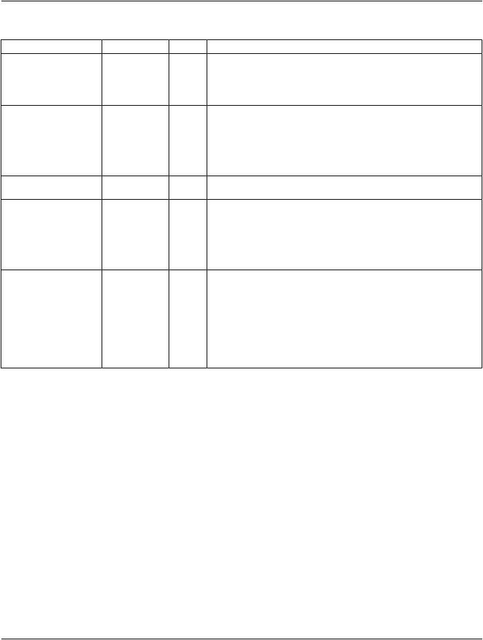
All geometric values in Table C.36.2.2.9-1 are defined in the Beam Modifier Definition Plane.​

C.36.2.2.9.1.2 RT Beam Delimiter Element Positions​

For Device Type Code Sequence (3010,002E) values of (130330, DCM, "Jaw Pair") or (130331, DCM, "Leaf Pairs"), the order of​ values are​

N1, N2, Nn​

P1, P2, Pn​

where N denotes the negative mounting side, P the positive mounting side and the indices increasing corresponding to the order of​ the values of Parallel RT Beam Delimiter Boundaries (300A,0649).​

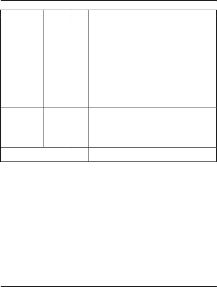
C.36.2.2.9.1.3 RT Beam Delimiter Geometry​

The definition of the tip positions in Parallel RT Beam Delimiter Positions (300A,064A) or delimiter outline in the RT Beam Delimiter​ Geometry Sequence (300A,064C) is as defined by the manufacturer and shall be documented in the Conformance Statement. Typ-​ ically, this will be the radiological or physical edge.​

- Standard -​

DICOM PS3.3 2020a - Information Object Definitions​

Page 1613​

C.36.2.2.10 Wedges Definition Macro​

This Macro defines the geometric configuration elements which cannot vary during delivery.​

Table C.36.2.2.10-1. Wedges Definition Macro Attributes​

Attribute Name​

Tag​

Type​

Attribute Description​

Number of Wedges​

(300A,00D0)​

1C​

Number of Wedges defined in the Wedge Definition Sequence​


(300A,0651).​


Required if RT Radiation Physical and Geometric Content Detail Flag​


(300A,0638) equals FULL. May be present otherwise.​

WedgeDefinitionSequence​

(300A,0651)​

1C​

Treatment wedge definitions.​


Required if Number of Wedges (300A,00D0) is present and has a​


non-zero value.​


The number of Items included in this Sequence shall equal the value​


of Number of Wedges(300A,00D0).​

>Include Table C.36.2.2.3-1 “RT Accessory Device​

DCID 9546 “Radiotherapy Wedge Types”.​

Identification Macro Attributes”.​


>Device Index​

(3010,0039)​

1​

Index of this Itemin this Sequence.​


The value shall start at 1 and increase monotonically by 1.​

>Referenced Defined​

(300A,0602)​

1C​

DeviceIndexvaluethatlinksthedevicedefinedbythisSequenceItem​

Device Index​


to the corresponding device in an RT Radiation Instance. The​


description of the two devices may or may not be the same.​


The value is the index of a device in the Wedges Definition Sequence​


(300A,0651)withinthesingleSOPInstancereferencedbyReferenced​


RT Instance Sequence (300A,0631).​


Required if the Instance referenced in Referenced RT Instance​


Sequence (300A,0631) contains the device that corresponds to the​


device defined by this Sequence Item.​

>Radiation Beam Wedge​

(300A,0652)​

1​

Nominal wedge angle in degrees.​

Angle​


See Section C.36.2.2.10.1.1.​


>Radiation Beam Effective​

(300A,0654)​

2​

Effective wedge angle in degrees.​

Wedge Angle​


See Section C.8.8.14.14.​


>BeamModifierOrientation​

(300A,0645)​

1​

AngleindegreesoftheBeamModifierCoordinateSystemwithrespect​

Angle​


to the Base Beam Modifier Coordinate System. The angle is a​


Continuous Rotation Angle, see Section C.36.1.1.5.​

The direction from thick edge to thin edge is along the positive y-axis​ of the Beam Modifier Definition Plane.​

See Section C.36.1.1.9 and Section C.36.2.2.10.1.1.​

C.36.2.2.10.1 Wedges Definition Macro Attribute Description​

C.36.2.2.10.1.1 Radiation Beam Wedge Orientation and Radiation Beam Wedge Angle​

For an Equipment Frame of Reference UID 1.2.840.10008.1.4.3.1 the wedge orientation has the value of 0 degree when the thin​ edge of the wedge is directed towards the positive direction of the y-axis of the Beam Modifier Coordinate system.​

- Standard -​

Page 1614​

DICOM PS3.3 2020a - Information Object Definitions​

+Z

Radiation source

Beam Modifier Orientation Angle (300A,0645) value = 0º

Plane

Figure C.36.2.2.10.1-1. Beam Modifier Orientation Angle​

+Z

Radiation Source

Wedge

Isodose Line measured in water (e.g., at 50%)

Radiation Beam Wedge Angle

(300A,0652)

Beam Central Axis

Figure C.36.2.2.10.1-2. Radiation Beam Wedge Angle​

C.36.2.2.11 Wedge Positions Macro​

This Macro defines the positions of Wedges used in a specific Control Point or set of Control Points.​

- Standard -​

DICOM PS3.3 2020a - Information Object Definitions​ Page 1615​

Table C.36.2.2.11-1. Wedge Positions Macro Attributes​

Attribute Name​

Tag​

Type​


Attribute Description​

Number of Wedge​

(300A,0655)​

1C​

Number of Wedge Positions defined in the Wedge Position Sequence​

Positions​


(300A,0116).​


Required if Number of Wedges (300A,00D0) is present and has a non-zero​


value.​


Wedge Position Sequence​ (300A,0116)​

1C​

Position for each Wedge for the current Control Point.​


Required if Number of Wedge Positions (300A,0655) is present and has a​


non-zero value and the conditions in Section C.36.2.2.5.1.1 are satisfied.​


The number of Items included in this Sequence shall equal the value of​


Number of Wedge Positions (300A,0655).​

>ReferencedDeviceIndex​ (300A,0607)​

1​

The value of Device Index (3010,0039) in Wedge Definition Sequence​


(300A,0651) for the Wedge being used.​

>Wedge Position​

(300A,0118)​

1​

Position of Wedge at current Control Point.​


Enumerated Values:​


IN​

Thecompensatorsurfaceshapeisdirectedtowardsthepatient.​


OUT​

The wedge is in fully retracted position.​


PARTIAL​The wedge is inserted only part of the way.​

>Radiation Beam Wedge​

(300A,0653)​

1C​

Closest distance in mm from the central axis of the beam along the wedge​

Thin Edge Distance​


angle direction to the thin edge as projected on the Beam ModifierDefinition​


Plane defined by the RT Beam Modifier Definition Distance (300A,0688).​

The value is negative if the thin edge is located on the positive y-axis, and​ is positive otherwise.​

Required if Wedge Position (300A,0118) is PARTIAL.​

See Section C.36.2.2.11.1.1.​

- Standard -​