Материал: part03

Внимание! Если размещение файла нарушает Ваши авторские права, то обязательно сообщите нам

Page 1616​

DICOM PS3.3 2020a - Information Object Definitions​

C.36.2.2.11.1 Wedge Positions Macro Attribute Descriptions​

C.36.2.2.11.1.1 Radiation Beam Wedge Thin Edge Distance​

+Z

Radiation Source

Wedge

Wedge

Base Beam Modifier Definition Plane

Negative

Positive

Figure C.36.2.2.11.1-1. Radiation Beam Wedge Thin Edge Position​

C.36.2.2.12 Compensators Definition Macro​

This Macro defines the geometric configuration elements which cannot vary during delivery.​

Table C.36.2.2.12-1. Compensators Definition Macro Attributes​

Attribute Name​

Tag​

Type​

Attribute Description​

Number of Compensators​

(300A,00E0)​

1C​

NumberofCompensatorsdefinedintheCompensatorDefinitionSequence​


(300A,0662).​


Required if RT Radiation Physical and Geometric Content Detail Flag​


(300A,0638) equals FULL. May be present otherwise.​

Compensator Definition​

(300A,0662)​

1C​

Treatment compensator definitions.​

Sequence​


Required if Number of Compensators (300A,00E0) is present and has a​


non-zero value.​


The number of Items included in this Sequence shall equal the value​


ofNumber of Compensators (300A,00E0).​

>Include Table C.36.2.2.3-1 “RT Accessory Device​

DCID 9542 “Compensator Device Types”.​

Identification Macro Attributes”.​


>Device Index​

(3010,0039)​

1​

Index of the Device in this Sequence.​


The value shall start at 1 and increase monotonically by 1.​

- Standard -​


DICOM PS3.3 2020a - Information Object Definitions​

Page 1617​

Attribute Name​

Tag​

Type​

Attribute Description​


>Referenced Defined​

(300A,0602)​

1C​

Device Index value that links the device defined by this Sequence Item to​

Device Index​


the corresponding device in an RT Radiation Instance. The description of​


the two devices may or may not be the same.​


ThevalueistheindexofadeviceintheCompensatorDefinitionSequence​


(300A,0662)withinthesingleSOPInstancereferencedbyReferencedRT​


Instance Sequence (300A,0631).​


Required if the Instance referenced in Referenced RT Instance Sequence​


(300A,0631) contains the device that corresponds to the device defined​


by this Sequence Item.​


>Beam Modifier​

(300A,0645)​

1​

Angle in degrees of the Beam Modifier Coordinate System with respect to​

Orientation Angle​


the Base Beam Modifier Coordinate System. The angle is a Continuous​


Rotation Angle, see Section C.36.1.1.5.​


See Section C.36.1.1.9.​


>CompensatorBasePlane​ (300A,0666)​

1C​

The distance in mm between the mounting plane and the base plane of​

Offset​


the compensator.​


The value shall be positive when the base plane is farther away from the​


referencelocation(asspecifiedbyRTDeviceDistanceReferenceLocation​


Code Sequence (300A,0659) ) than the mounting plane.​


Required if RT Radiation Physical and Geometric Content Detail Flag​


(300A,0638) equals FULL. May be present otherwise.​


See Section C.36.2.2.12.1.2.​


>Compensator Map​

(300A,0663)​

1C​

Side of the compensator base that the compensator surface shape faces.​

Orientation​


Enumerated Values:​


PATIENT_SIDE​Thecompensatorsurfaceshapeisdirectedtowardsthe​


patient.​


SOURCE_SIDE​Thecompensatorsurfaceshapeisdirectedtowardsthe​


Radiation Source.​


DOUBLE_SIDED​Thecompensatorhastwocompensatorsurfaceshapes​


which are directed towards the patient and source​


respectively.​


Required if RT Radiation Physical and Geometric Content Detail Flag​


(300A,0638) equals FULL. May be present otherwise.​


>Compensator Shape​

(300A,0668)​

1C​

Description of the shape of the Compensator and the fabrication​

Sequence​


parameters.​


Required if RT Radiation Physical and Geometric Content Detail Flag​


(300A,0638) equals FULL. May be present otherwise.​


Only one Item shall be present.​


>>Compensator​

(300A,02E0)​

1​

Whether or not the compensator is shaped according to the beam​

Divergence​


geometrical divergence.​


Enumerated Values:​

PRESENT​Thecompensatorisshapedaccordingtothebeamgeometrical​ divergence.​

ABSENT​The compensator is not shaped according to the beam​ geometrical divergence.​

- Standard -​

Page 1618​

DICOM PS3.3 2020a - Information Object Definitions​

Attribute Name​

Tag​

Type​

Attribute Description​

>>Material ID​

(300A,00E1)​

2​

User-defined identifier for the material used to manufacture the​


Compensator.​

>>Compensator Proximal​

(300A,0664)​

1C​

A data stream of triplets of x, y and thickness in mm representing a map​

Thickness Map​


of the coordinates in the Beam Modifier Definition Plane and thicknesses​


from the compensator base plane. The order of triplets is not significant.​


RequiredifCompensatorMapOrientation(300A,0663)isSOURCE_SIDE​


or DOUBLE_SIDED.​


See Section C.36.2.2.12.1.1 and Section C.36.2.2.12.1.3.​

>>Compensator Distal​

(300A,0665)​

1C​

A data stream of triplets of x, y and thickness in mm representing a map​

Thickness Map​


of the coordinates in the Beam Modifier Definition Plane and thicknesses​


from the compensator base plane. The order of triplets is not significant.​


Required if Compensator Map Orientation (300A,0663) is PATIENT_SIDE​


or DOUBLE_SIDED.​


See Section C.36.2.2.12.1.1 and Section C.36.2.2.12.1.3.​

>>Compensator Shape​

(300A,0667)​

2​

The method of fabrication, such as shape of tools to be used, surface​

Fabrication Code​


modelling technique.​

Sequence​


Zero or more Items shall be included in this Sequence.​


>>>Include Table 8.8-1 “Code Sequence Macro​

No Baseline CID is defined.​

Attributes”.​


>>Radiation Beam​

(300A,0669)​

2​

Thediameterinmmofthemillingtooltobeusedtocreatethecompensator.​

Compensator Milling Tool​


The diameter is expressed as the actual physical size and not a size​

Diameter​


projected on the Beam ModifierDefinition Plane.​

C.36.2.2.12.1 Compensators Definition Macro Attribute Descriptions​

C.36.2.2.12.1.1 Compensators Thickness Map and Tray Distance​

ThethicknessvaluesstoredinCompensatorProximalThicknessMap(300A,0664)andCompensatorDistalThicknessMap(300A,0665)​ shall be specified parallel to the radiation beam axis if Compensator Divergence (300A,02E0) equals ABSENT, or specified according​ to the beam geometrical divergence if Compensator Divergence (300A,02E0) equals PRESENT.​

C.36.2.2.12.1.2 Compensator Base Plane Offset​

The compensator base plane is the side of the compensator which is flat. In case of a double-sided compensator, the base plane is​ the plane from which the compensator thickness is specified.​

- Standard -​

DICOM PS3.3 2020a - Information Object Definitions​

Page 1619​


+Z


Block Orientation


(300A,066C)


= SOURCE_SIDE


Block Thickness


Compensator Mounting Plane


(300A,0100)


Block and Compensator Tray in Accessory Slot


Compensator Proximal Thickness Map


Compensator Base Plane

(300A,0664)


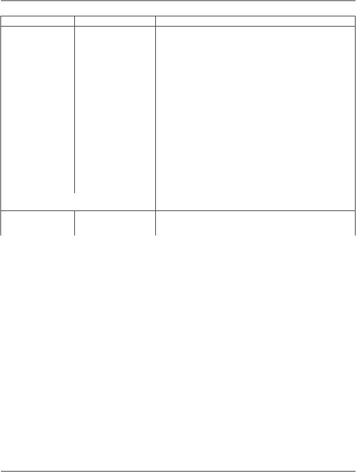
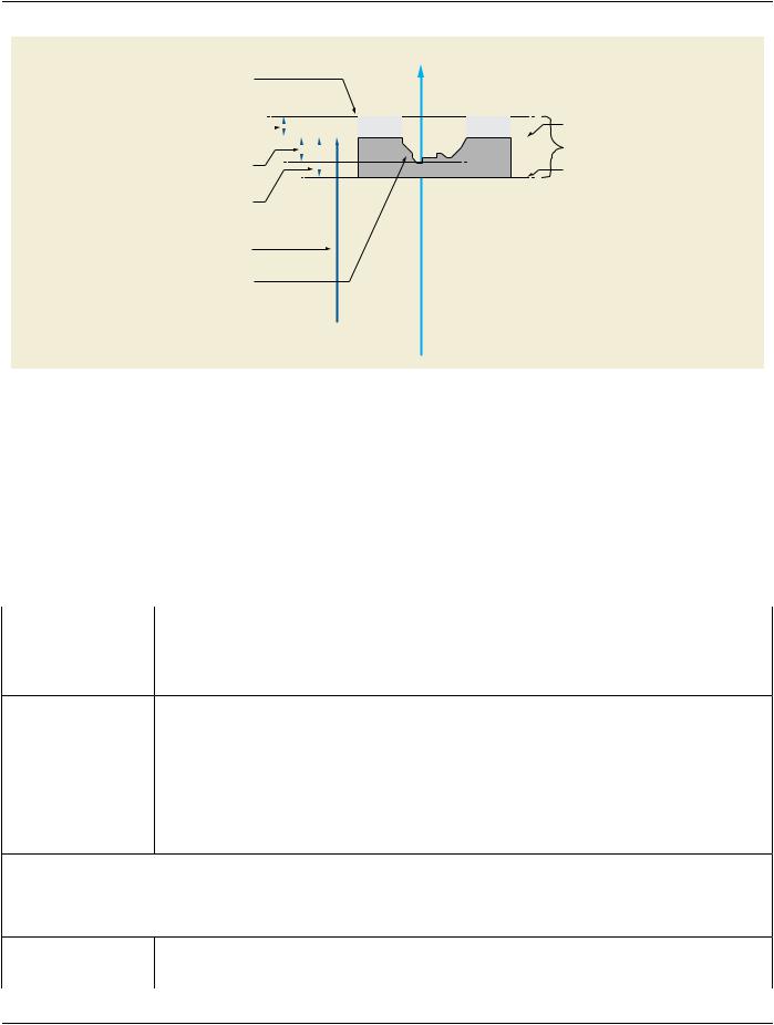
Compensator Base Plane Offset (300A,0666)

(Attribute value is negative)

RT Accessory Slot Distance

(300A,0613)

Compensator Map Orientation (300A,0663)

= SOURCE_SIDE

RT Device Distance Reference Location Code Sequence Isocenter (300A,0659)

code = (130359, DCM, “Treatment Machine Isocenter”)

Figure C.36.2.2.12.1-1. Example of Block and Compensator Geometry​

C.36.2.2.12.1.3 Compensator Thickness Data Direction​

The direction of the rows and columns in Compensator Proximal Thickness Map (300A,0664) and Compensator Distal Thickness​ Map (300A,0665) is defined as follows: The direction of rows goes along the positive X direction and the direction of the columns​ goes along the negative Y direction of the Beam Modifier Coordinate System.​

C.36.2.2.13 Blocks Definition Macro​

This Macro defines the geometric configuration elements which cannot vary during delivery.​

Table C.36.2.2.13-1. Blocks Definition Macro Attributes​

Attribute Name​

Tag​

Type​

Attribute Description​

Number of Blocks​

(300A,00F0)​

1C​

Number of Blocks defined in the Block Definition Sequence (300A,066A).​


Required if RT Radiation Physical and Geometric Content Detail Flag​


(300A,0638) is FULL. May be present otherwise.​

Block Definition​

(300A,066A)​

1C​

Block definitions.​

Sequence​


Required if Number of Blocks (300A,00F0) is present and has a non-zero​


value.​


The number of Items included in this Sequence shall equal the value of​


Number of Blocks (300A,00F0).​


OnlyoneIteminthisSequenceshallhave(130123,DCM,"ApertureBlock")​


as the code value of Device Type Code Sequence (3010,002E).​

>Include Table C.36.2.2.3-1 “RT Accessory Device​

DCID 9517 “Radiotherapy Block Device Types”.​

Identification Macro Attributes”.​


The Device Alternate Identifier (3010,001B) Attribute of the RT Accessory​


Device Identification Macro shall not contain a value when the Number of​


Block Slab Items (300A,0440) is non-zero.​

>Device Index​

(3010,0039)​

1​

Index of the Device in this Sequence.​


The value shall start at 1 and increase monotonically by 1.​

- Standard -​

Page 1620​

DICOM PS3.3 2020a - Information Object Definitions​

Attribute Name​

Tag​

Type​

Attribute Description​

>Referenced Defined​

(300A,0602)​

1C​

Device Index value that links the device defined by this Sequence Item to​

Device Index​


the corresponding device in an RT Radiation Instance. The description of​


the two devices may or may not be the same.​


The value is the index of a device in the Block Definition Sequence​


(300A,066A) within the single SOP Instance referenced by Referenced RT​


Instance Sequence (300A,0631).​


Required if the Instance referenced in Referenced RT Instance Sequence​


(300A,0631) contains the device that corresponds to the device defined by​


this Sequence Item.​

>Beam Modifier​

(300A,0645)​

1​

Angle in degrees of the Beam Modifier Coordinate System with respect to​

Orientation Angle​


the Base Beam Modifier Coordinate System. The angle is a Continuous​


Rotation Angle, see Section C.36.1.1.5.​


See Section C.36.1.1.9.​

>Material ID​

(300A,00E1)​

2​

User-defined identifier for material used to manufacture the Block.​

>Block Divergence​

(300A,00FA)​

1C​

Whether or not the block is shaped according to the beam geometrical​


divergence.​


Enumerated Values:​


PRESENT​Block edges are shaped for beam divergence.​


ABSENT​Block edges are not shaped for beam divergence.​


Required if RT Radiation Physical and Geometric Content Detail Flag​


(300A,0638) equals FULL. May be present otherwise.​

>Block Orientation​

(300A,066C)​

1C​

Specifies on which side of the block base the block extends.​


Enumerated Values:​


PATIENT_SIDE​The block extends from its base towards the patient.​


SOURCE_SIDE​The block extends from its base towards the Radiation​


Source.​


Required if RT Radiation Physical and Geometric Content Detail Flag​


(300A,0638) equals FULL. May be present otherwise.​

>Radiation Beam Block​

(300A,066D)​

2C​

Physicalthicknessofblockinmmparalleltothecentralradiationbeamaxis.​

Thickness​


Required if Material ID (300A,00E1) has a value. May be present otherwise.​


>Block Edge Data​

(300A,066F)​

2​

Block Edge Data streams.​

Sequence​


ThepolygonsrepresentedbytheBlockEdgeData(300A,066B)datastreams​


in all Items in this Sequence shall be non-overlapping.​


Zero or more Items shall be included in this Sequence.​

>>Block Edge Data​

(300A,066B)​

1​

A data stream of coordinate pairs in mm representing a polygon which​


comprise the block edge.​

The polygon is implicitly closed from the last pair to the origin pair and all​ edges shall be non-intersecting except at the vertices. Any given coordinate​ pair shall only occur once in the data stream.​

Coordinates are projected on the Beam ModifierDefinition Plane.​

- Standard -​