Материал: part03

Внимание! Если размещение файла нарушает Ваши авторские права, то обязательно сообщите нам

DICOM PS3.3 2020a - Information Object Definitions​

Page 1241​

•​Detector Reference Point Od, is an arbitrary point, defined by the equipment manufacturer, that lies on the axis of rotation of the​ detector, if any.​

•​Xd axis lies in the plane parallel to the detector surface, through the point Od, and perpendicular to the axis of rotation. The +Xd​ direction is in the same direction as the +X direction when the detector surface is normal to gravity.​

•​Yd axis is the axis of rotation of the detector and is parallel to Y. The +Yd direction is in the same direction as the +Y direction when​ the detector surface is normal to gravity.​

•​Zd axis is normal to the detector surface and through the point Od. The +Zd direction is upward, defined by the right-hand rule from​ +Xd and +Yd.​


+Z


+Z


d


d


Od

+X

Od

+Y

d


d


Figure C.8.31.6-9. Detector Coordinate System​

The Detector coordinate system (Od, Xd, Yd, Zd) is characterized with respect to the Isocenter coordinate system (O, X, Y, Z), by two​ anglesdescribingthetiltofthedetector.TheseanglesarerelativetotheIsocenterreferencesystem,andindependentfromthepatient​ position on the equipment.​

Detector Isocenter Primary Angle (0018,9550) (so-called Ad1) is defined as the angle between the YZ plane and the YZd plane. The​ angle is positive when the +Xd axis is lower than the -Xd axis with respect to Z, and is 0°when the detector surface is normal to the​ +Z axis.​

Detector Isocenter Secondary Angle (0018,9551) (so-called Ad2) is defined as the angle between the plane XZ and the plane XZd.​ The angle is positive when the +Yd axis is lower than the -Yd axis with respect to Z. In most cases this angle is 0°, inferring that the​ XZ plane is parallel to the Xd plane.​

- Standard -​

Page 1242​

DICOM PS3.3 2020a - Information Object Definitions​

Ad1

Ad2


+Z

d


+Z


d

Od


+X

d

Od

+Y


d

Figure C.8.31.6-10. Detector Isocenter Angles​

DetectorXPositiontoIsocenter(0018,9552)(so-calledDX)isdefinedasthetranslationoftheDetectorReferencePointOd withrespect​ to the Isocenter coordinate system in the X direction. A translation of DX toward Breast Support Right from Detector Od is positive.​

DetectorYPositiontoIsocenter(0018,9553)(so-calledDY)isdefinedasthetranslationoftheDetectorReferencePointOd withrespect​ to the Isocenter coordinate system in the Y direction. A translation of DY toward Breast Support Anterior from Detector Od is positive.​

DetectorZPositiontoIsocenter(0018,9554)(so-calledDZ)isdefinedasthetranslationoftheDetectorReferencePointOd withrespect​ to the Isocenter coordinate system in the Z direction. A translation of DZ toward Breast Support Head from Detector Od is positive.​

- Standard -​

DICOM PS3.3 2020a - Information Object Definitions​

Page 1243​

O

(Dx,Dy,Dz)

O

Od


Od

O

(Dx1,Dy1,Dz1)

O


Od1


Od1


...


O


O


(Dxn,Dyn,Dzn)


Odn


Odn

Figure C.8.31.6-11. Translation of the Detector Coordinate System​

Although not shown in Figure C.8.31.6-11, translation of the detector moves the Detector Origin Od relative to the Isocenter. Thus​ during translation of the detector, at least one of DX, DY and DZ will change.​

- Standard -​

Page 1244​

DICOM PS3.3 2020a - Information Object Definitions​

Note​

A translation of (DX, DY, DZ) = (0, 0, 0) means that the Detector Reference Point Od is at the System Isocenter.​

The case where the detector is stationary during image acquisition is a degenerate case, but still defined in the same manner.​

Note​

1.​An angulation of (Ad1, Ad2) = (0, 0) means that the Detector is not rotated relative to the System Isocenter coordinate​ system.​

2.​A translation of (DX, DY, DZ) = (0, 0, 0) means that the Detector Reference Point Od is at the System Isocenter.​

C.8.31.6.1.5 Detector Active Area Relationship​

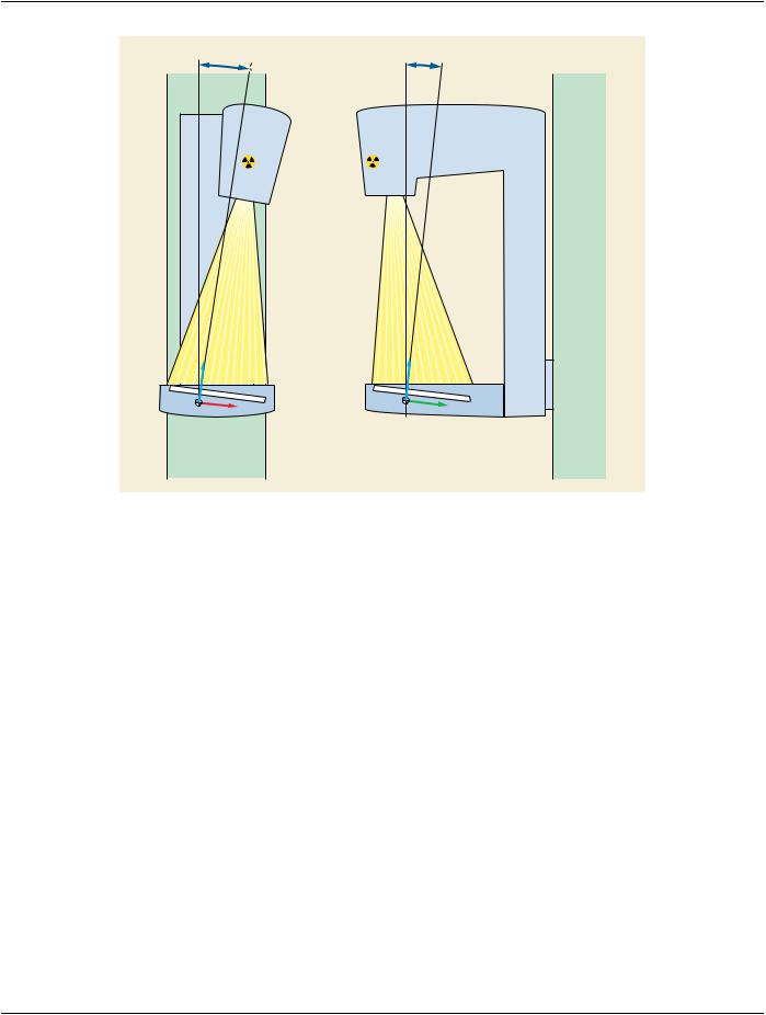
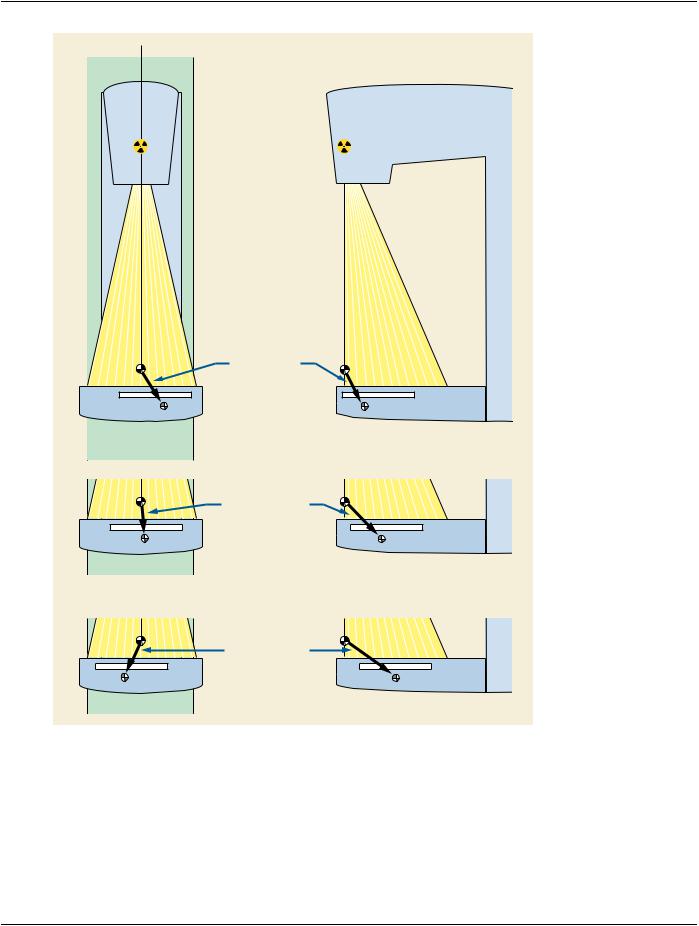
The image and planes in conventional mammography and digital breast tomosynthesis are expressed in relation to Detector FOV​ and Detector Active area (see C.8.11.4.1.1). As manufacturers design their systems differently, the detector may be mounted or po-​ sitioned differently in different breast imaging systems. As a result, the TLHC position of the Detector Active Area, together with row​ and column directions, must be specified (see Figure C.8.31.6-12). The relationship between the Detector Active Area TLHC, the row​ and column directions of the Active Area, and the Field of View and Detector Coordinate System (defined in C.8.31.6.1.4) is defined​ by two Attributes.​

•​Detector Active Area TLHC Position (0018,9557) specifies the x, y and z cooordinates in mm of the center of the pixel defined as​ Detector Active Area TLHC within the Detector coordinate system, where the Z-direction value is always 0 since the detector itself​ is in XdYd plane. A value of Detector Active Area TLHC Position (0018,9557) = (0,0,0) means that the Detector Active Area TLHC​ Position is at the origin Od of the Detector coordinate system.​

•​Detector Active Area Orientation (0018,9558) specifies the direction cosines of the first row followed by the direction cosines of the​ first column within the Detector coordinate system. The first three values contain the cosine of the angle between the first row and​ the Xd, Yd and Zd axes, respectively. The next three values contain the cosine of the angle between the first column and the Xd, Y​ d and Zd axes, respectively.​


Yd


Yd


Column Direction


Detector

TLHC


Detector


Active


Active


Area


Row

Row


Area


Direction


Direction


Od


Xd


Od

Xd


TLHC


Column Direction

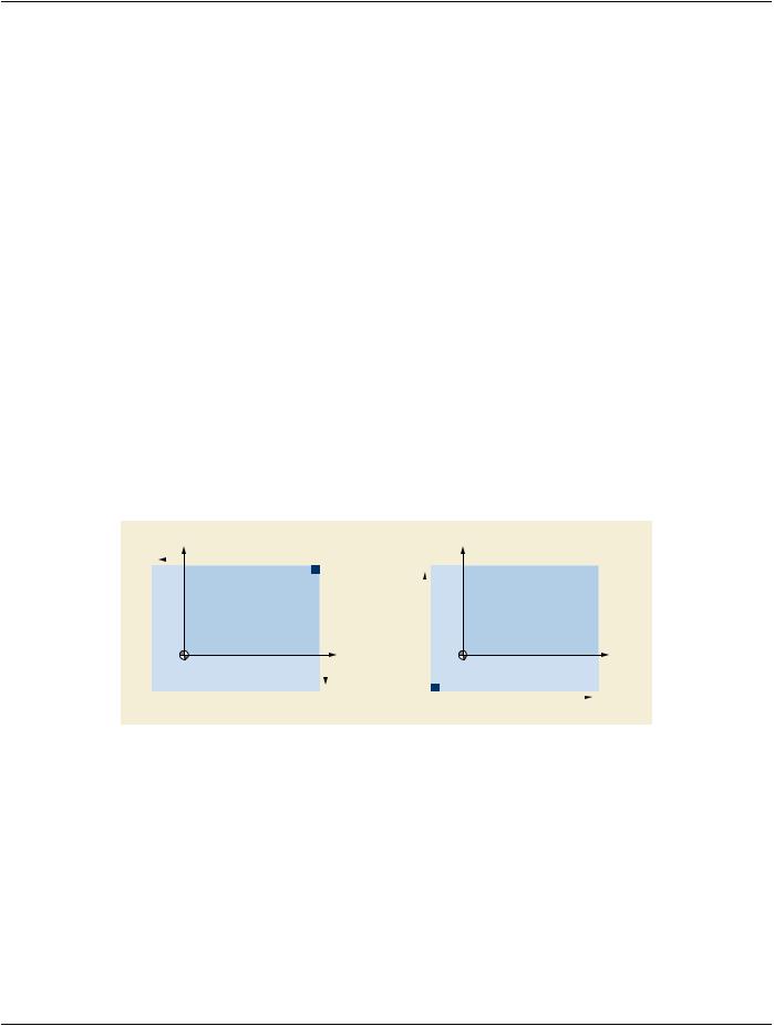
Figure C.8.31.6-12. Examples of Detector Active Area TLHC Position and Orientation​

In Figure C.8.31.6-12, the left picture illustrates Detector Active Area Orientation (0018,9558) = (0,-1,0,-1,0,0), while the right picture​ illustrates Detector Active Area Orientation (0018,9558) = (0,1,0,1,0,0).​

C.8.31.7 X-Ray Grid Macro​

Table C.8.31.7-1 specifies the Attributes of the X-Ray Grid Functional Group Macro.​

- Standard -​

DICOM PS3.3 2020a - Information Object Definitions​ Page 1245​

Table C.8.31.7-1. X-Ray Grid Macro Attributes​

Attribute Name​

Tag​

Type​

Attribute Description​

X-Ray Grid Sequence​

(0018,9555)​

1​

A Sequence that describes the geometrical position of​


the positioner.​


Only a single Item shall be included in this Sequence.​

>Grid​

(0018,1166)​

1​

Identified the grid. May be multi-valued.​


Defined Terms:​

FIXED​

FOCUSED​

RECIPROCATING​

PARALLEL​

CROSSED​

NONE​

Include Table C.8-36b “X-Ray Grid Description Macro Attributes”​

C.8.31.8 X-Ray Filter Macro​

Table C.8.31.8-1 specifies the Attributes of the X-Ray Filter Functional Group Macro.​

Table C.8.31.8-1. X-Ray Filter Macro Attributes​

Attribute Name​

Tag​

Type​

Attribute Description​

X-Ray Filter Sequence​

(0018,9556)​

1​

A Sequence that describes the Attributes related to​


the filtration of X-Rays during image acquisition.​

OnlyasingleItemshallbeincludedinthisSequence.​

> Include Table C.8-35a “X-Ray Filtration Macro Attributes”​

C.8.32 Parametric Map​

This section describes the specific Modules for the Parametric Map IOD.​

C.8.32.1 Parametric Map Series Module​

Table C.8.32-1 defines the general Attributes of the Parametric Map Series Module.​

Table C.8.32-1. Parametric Map Series Module Attributes​

Attribute Name​

Tag​

Type​

Attribute Description​

Modality​

(0008,0060)​

1​

Modality type​


Note​


1.​It is expected that the majority of Parametric Maps​


will use the appropriate value for the acquisition​


modality, e.g., "MR", and so no specific Defined​


Terms or Enumerated Values are specified here.​

2.​Iftheimageisderivedfrommultiplemodalities,then​ a value of "OT" is appropriate.​

Series Number​

(0020,0011)​

1​

A number that identifies this Series​

- Standard -​