Page 1238 |
DICOM PS3.3 2020a - Information Object Definitions |
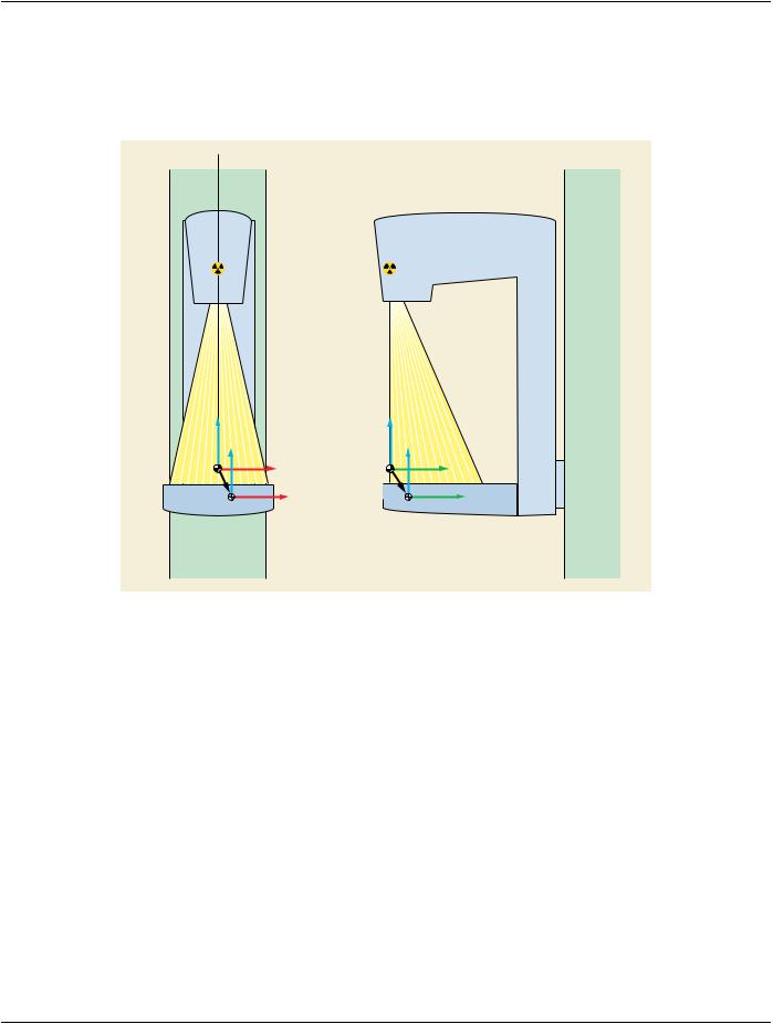
C.8.31.6.1.3 Breast Support Coordinate System
The Breast Support (see Figure C.8.31.6-6) is the housing over the detector onto which the breast is placed before imaging. For the purpose of this description, Breast Support top surface refers to the patient contact surface of the Breast Support, closest to the X- Ray source.
Figure C.8.31.6-6. Breast Support Orientation
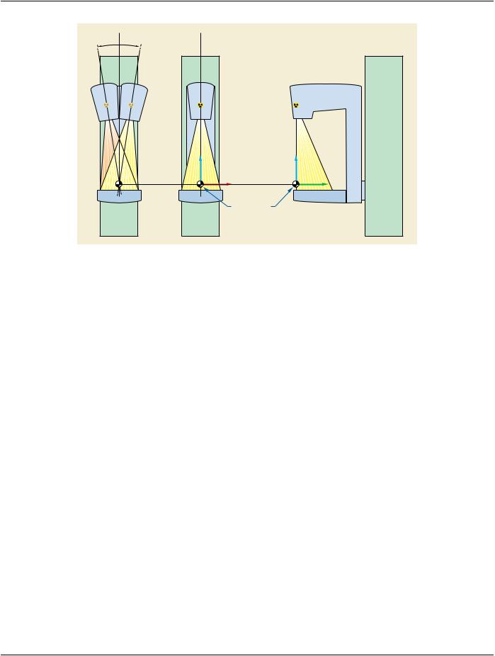
The Breast Support coordinate system (Ob, Xb, Yb, Zb) is defined as follows (see Figure C.8.31.6-7):
•Origin Ob, the so-called Breast Support Reference Point, is an arbitary point, as defined by the equipment manufacturer, on the axis of the center of rotation of the Breast Support.
•Xb axis lies parallel to the Breast Support top surface, passes through Ob, and is parallel to X when the Breast Support top surface is normal to gravity. The +Xb direction is toward BREAST SUPPORT RIGHT.
•Yb axis lies parallel to the Breast Support top surface, passes through Ob, and is perpendicular to the Xb axis. The +Yb direction is toward BREAST SUPPORT ANTERIOR.
•Zb axis is normal to the Breast Support top surface and passes through Ob. The +Zb direction is toward BREAST SUPPORT HEAD.
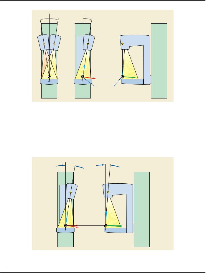
The Breast Support coordinate system (Ob, Xb, Yb, Zb) is characterized, with respect to the Isocenter coordinate system (O, X, Y, Z), by two rotations that describe the Breast Support tilt and a 3D translation (see Figure C.8.31.6-7). It is the most common convention in breast projection X-Ray system design to have the Breast Support rotate identically and in synchronization with the system C-arm (they are most often rigidly integrated):
Breast Support Isocenter Primary Angle (0018,9545) (so-called Ab1) is defined as the angle between the YZ plane and the YZb plane. The angle is positive when the Breast Support Right end of the Breast Support is lower than the Breast Support Left end of the Breast Support, and is 0° when the Breast Support surface is normal to the +Z direction. In digital breast tomosynthesis, because the X-Ray sourcemovesindependentlyoftheBreastSupport,theBreastSupportIsocenterPrimaryAngleistheprincipalplacewheretheuser's perception of the C-arm angle is encoded.
Breast Support Isocenter Secondary Angle (0018,9546) (so-called Ab2) is defined as the angle between the XY plane and the XYb plane. The angle is positive when the Breast Support Anterior side of the Breast Support is lower than the Breast Support Posterior endoftheBreastSupport,andis0°whentheBreastSupportsurfaceisnormaltothe+Zaxis.InmostbreastprojectionX-Rayimaging equipment the value of Ab2 is 0°.

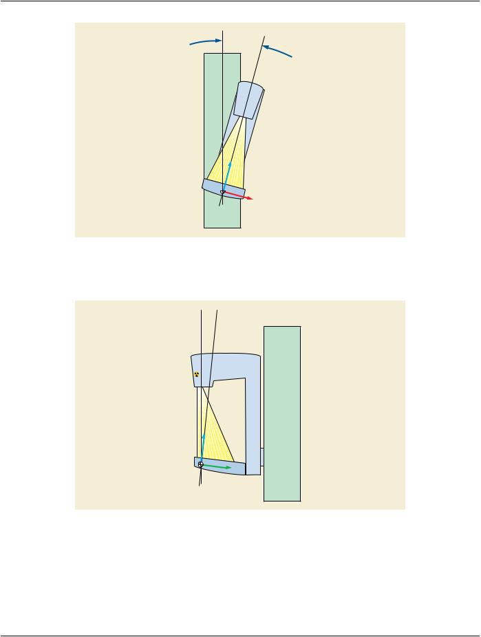

 Ab
Ab