Материал: part03

Внимание! Если размещение файла нарушает Ваши авторские права, то обязательно сообщите нам


DICOM PS3.3 2020a - Information Object Definitions​

Page 1231​

Attribute Name​

Tag​

Type​

Attribute Description​


>Exposure in mAs​

(0018,9332)​

1​ The exposure expressed in mAs, for example calculated from Exposure Time​


and X-Ray Tube Current.​


>Relative X-Ray​

(0018,1405)​

3​ Indication of the applied dose, in manufacturer specific units.​


Exposure​


Note​


1.​This value is intended to provide a single location where​


manufacturer specific information can be found for annotation​


on a display or film, that has meaning to a knowledgeable​


observer.​


2.​This may be a calculated or measured value. Examples are the​


detectorentrancedose(KB),theCRsensitivityvalue(S),orthe​


logarithmic median (lgM).​


3.​DICOM specifies Standard Attributes in Table 10-23 “Exposure​


Index Macro Attributes”, which are recommended.​


>Half Value Layer​

(0040,0314)​

3​ The thickness of Aluminum in mm required to reduce the X-Ray Output​


(0040,0312) by a factor of two.​


Note​


This value may be a calibrated value rather than measured during​


the exposure.​


>Organ Dose​

(0040,0316)​

1​ Average organ dose value measured in dGy during the acquisition of this​


image.​


Note​


This may be an estimated value.​


>Entrance Dose in mGy​

(0040,8302)​

1​ Average entrance dose value measured in mGy at the surface of the patient​


during the acquisition of this image.​


Note​


This may be an estimated value based on assumptions about the​


patient's body size and habitus.​


>Entrance Dose​

(0040,8303)​

3​ Describes what type of dose is represented by the values of Entrance Dose​

Derivation​


in mGy (0040,8302).​


Enumerated Values:​


IAK​

Represents air kerma at the entrance surface, no backscatter​


included, no air kerma to tissue dose conversion applied.​


ESAK​ Represents air kerma at the entrance surface, with backscatter​

included, no air kerma to tissue dose conversion applied.​ ESDBS​ Represents absorbed dose in tissue at the entrance surface, with​

backscatter included.​

ESDNOBS​Represents absorbed dose in tissue at the entrance surface,​ without backscatter included.​

C.8.31.6 Breast X-Ray Isocenter Reference System Macro​

Table C.8.31.6-1 specifies the Attributes of the Breast X-Ray Isocenter Reference System Functional Group Macro.​

- Standard -​

Page 1232​ DICOM PS3.3 2020a - Information Object Definitions​

Table C.8.31.6-1. Breast X-Ray Isocenter Reference System Macro Attributes​

Attribute Name​

Tag​

Type​

Attribute Description​

Isocenter Reference System​

(0018,9462)​

1​ ASequencethatdescribestheIsocenterReferenceCoordinateSystem​

Sequence​


(O, X, Y, Z).​


Only a single Item shall be included in this Sequence.​

>X-Ray Source Isocenter​

(0018,9543)​

1​ Primary angle of the X-Ray source in the isocenter reference system​

Primary Angle​


(deg).​


See C.8.31.6.1.2 for further explanation.​

>X-Ray Source Isocenter​

(0018,9544)​

1​ SecondaryangleoftheX-Raysourceintheisocenterreferencesystem​

Secondary Angle​


(deg).​


See C.8.31.6.1.2 for further explanation.​

>Breast Support Isocenter​

(0018,9545)​

1​ PrimaryangleoftheBreastSupportintheisocenterreferencesystem​

Primary Angle​


(deg).​


See C.8.31.6.1.3 for further explanation.​

>Breast Support Isocenter​

(0018,9546)​

1​ Secondary angle of the Breast Support in the isocenter reference​

Secondary Angle​


system (deg).​

See C.8.31.6.1.3 for further explanation.​

>Breast Support X Position to​ (0018,9547)​ Isocenter​

1C​ X position of the Breast Support Reference Point with respect to the​ Isocenter (mm).​

See C.8.31.6.1.3 for further explanation.​

Required if Presentation Intent Type (0008.0068) = FOR​ PROCESSING. May be present otherwise.​

>Breast Support Y Position to​

(0018,9548)​

1C​

Y position of the Breast Support Reference Point with respect to the​

Isocenter​


Isocenter (mm).​


See C.8.31.6.1.3 for further explanation.​


Required if Presentation Intent Type (0008.0068) = FOR​


PROCESSING. May be present otherwise.​

>Breast Support Z Position to​

(0018,9549)​

1C​

Z position of the Breast Support Reference Point with respect to the​

Isocenter​


Isocenter (mm).​


See C.8.31.6.1.3 for further explanation.​


Required if Presentation Intent Type (0008.0068) = FOR​


PROCESSING. May be present otherwise.​

>Detector Isocenter Primary​

(0018,9550)​

1​

PrimaryangleoftheDetectorintheisocenterreferencesystem(deg).​

Angle​


See C.8.31.6.1.4 for further explanation.​


>Detector Isocenter Secondary​

(0018,9551)​

1​

Secondary angle of the Detector in the in the isocenter reference​

Angle​


system (deg).​

See C.8.31.6.1.4 for further explanation.​

- Standard -​


DICOM PS3.3 2020a - Information Object Definitions​

Page 1233​

Attribute Name​

Tag​

Type​

Attribute Description​


>Detector X Position to​

(0018,9552)​

1C​

XpositionoftheDetectorReferencePointwithrespecttotheIsocenter​

Isocenter​


(mm).​


See C.8.31.6.1.4 for further explanation.​


Required if Presentation Intent Type (0008.0068) = FOR​


PROCESSING. May be present otherwise.​


>Detector Y Position to​

(0018,9553)​

1C​

YpositionoftheDetectorReferencePointwithrespecttotheIsocenter​

Isocenter​


(mm).​


See C.8.31.6.1.4 for further explanation.​


Required if Presentation Intent Type (0008.0068) = FOR​


PROCESSING. May be present otherwise.​


>DetectorZPositiontoIsocenter​

(0018,9554)​

1C​

ZpositionoftheDetectorReferencePointwithrespecttotheIsocenter​


(mm).​


See C.8.31.6.1.4 for further explanation.​


Required if Presentation Intent Type (0008.0068) = FOR​


PROCESSING. May be present otherwise.​


>Detector Active Area TLHC​

(0018,9557)​

1C​

The x, y, and z coordinates in mm of the center of the top left hand​

Position​


corner detector element of the detector active area in the Detector​


coordinate system.​


See C.8.31.6.1.5 for further explanation.​


Required if Presentation Intent Type (0008.0068) = FOR​


PROCESSING. May be present otherwise.​


>Detector Active Area​

(0018,9558)​

1C​

The direction cosines of the first row and the first column with respect​

Orientation​


to the Detector coordinate system.​


See C.8.31.6.1.5 for further explanation.​

Required if Presentation Intent Type (0008.0068) = FOR​

PROCESSING. May be present otherwise.​

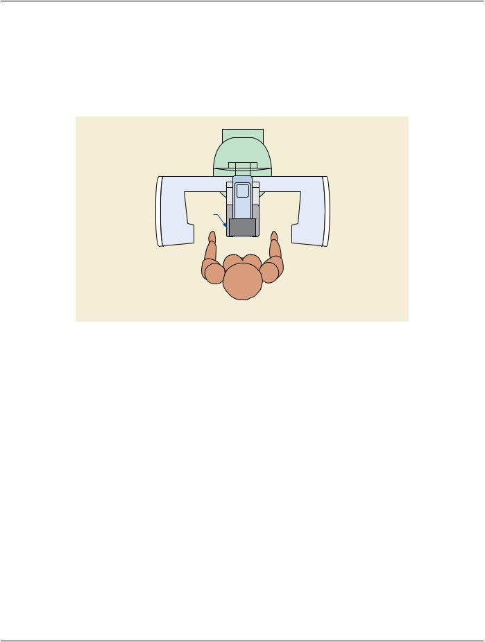
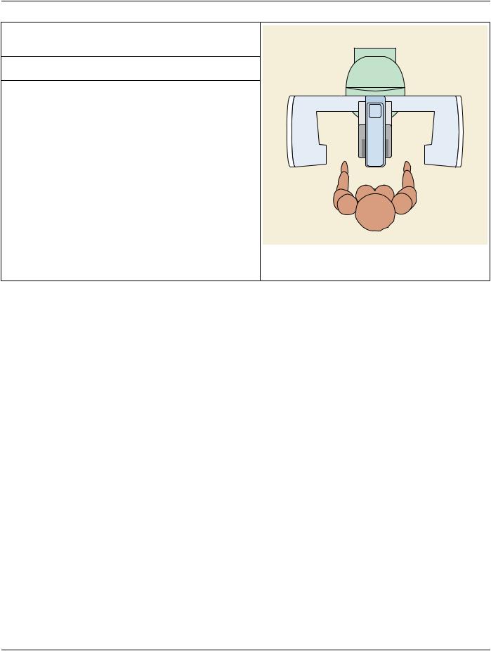
C.8.31.6.1 Isocenter Reference System Attribute Descriptions​

TheIsocenterReferenceSystemAttributesdescribethe3DgeometryoftheX-RayequipmentcomposedbytheX-RaySource,Breast​

Support and the Detector.​

These Attributes define four coordinate systems in the 3D space:​

•​Isocenter coordinate system​

•​X-Ray Source coordinate system​

•​Breast Support coordinate system​

•​Detector coordinate system​

The Isocenter Reference System Attributes describe the relationship between the 3D coordinates of a point in the Breast Support​ coordinate system and the 3D coordinates of such point in the X-Ray Source and Detector coordinate systems (which may move in​ the equipment), by using the Isocenter coordinate system that is fixed in the equipment.​

Unlike in X-Ray Angiography, in stereotactic biopsy and breast tomosynthesis the X-Ray source does not move in lock-step with the​ detector.Thedetectormaybestationary,maytranslate,ormayrotateastheX-Raysourcemoves.Thusforthepurposeofstereotactic​

- Standard -​

Page 1234​

DICOM PS3.3 2020a - Information Object Definitions​

biopsyandbreasttomosynthesis,theX-RaySourceandDetectorCoordinateSystemsaredefinedseparately,andeachofthepotential​ detector positionings is considered separately.​

Note​

Annex Z “X-Ray Isocenter Reference Transformations (Informative)” in PS3.17 describes the transformations necessary to​ transpose between coordinate systems.​

The detector is anterior to the patient standing upright and facing the front of the gantry, as shown in Figure C.8.31.6-1.​

Detector

Chest Wall

Patient Left

Patient Right

Patient Posterior

Figure C.8.31.6-1. Patient/Detector Relationship (Patient Standing)​

As breast projection X-Ray imaging traditionally uses devices with similar physical appearance, the following terms are defined for​ the purpose of helping later convey the geometry associated with breast projection X-Ray imaging:​

- Standard -​

DICOM PS3.3 2020a - Information Object Definitions​

Page 1235​

GANTRY FRONT​The side of the equipment closest to the patient​

whenthepatientisstanding,positionedforbreast​ Gantry Rear projection X-Ray imaging.​

GANTRY RIGHT​ The right-hand side of the equipment when the​ patient is standing facing GANTRY FRONT.​

GANTRY LEFT​

The left-hand side of the equipment when the​


patient is standing facing GANTRY FRONT.​


GANTRY REAR​

Thesideoftheequipmentfurthestfromthepatient​


whenthepatientisstanding,positionedforbreast​


projection X-Ray imaging.​

Gantry Left


Gantry Right


Gantry Front

Figure C.8.31.6-2. Gantry Sides​

C.8.31.6.1.1 Isocenter Coordinate System​

The Isocenter coordinate system (O,X,Y,Z) of the equipment is defined as follows (see Figure C.8.31.6-3) :​

•​OriginOistheSystemIsocenter,whichisthepointwheretheplaneofmotionoftheX-RaySourcespotintersectstheaxisofrotation​ of the X-Ray Source.​

•​+X direction is from GANTRY LEFT to GANTRY RIGHT in the horizontal plane (gravity plane).​

•​+Y direction is from GANTRY FRONT to GANTRY REAR in the horizontal plane (gravity plane).​

•​+Z direction is upward (anti-gravity).​

•​The isocenter coordinate system does not rotate when the tube head or C-arm rotates.​

- Standard -​