Материал: part03

Внимание! Если размещение файла нарушает Ваши авторские права, то обязательно сообщите нам

DICOM PS3.3 2020a - Information Object Definitions​

Page 1221​

C.8.30.3.1.3 Source Image Corneal Processed Data Sequence​

The Source Image Corneal Processed Data Sequence (0046,0244) provides power, elevation and wavefront measurements taken​ at specific points of the Source Image. These Attributes were used to generate the corneal topography map and indices of this SOP​ Instance. This processed data can also be used to generate other corneal topography maps and indices.​

C.8.30.3.1.4 Corneal Vertex Location​

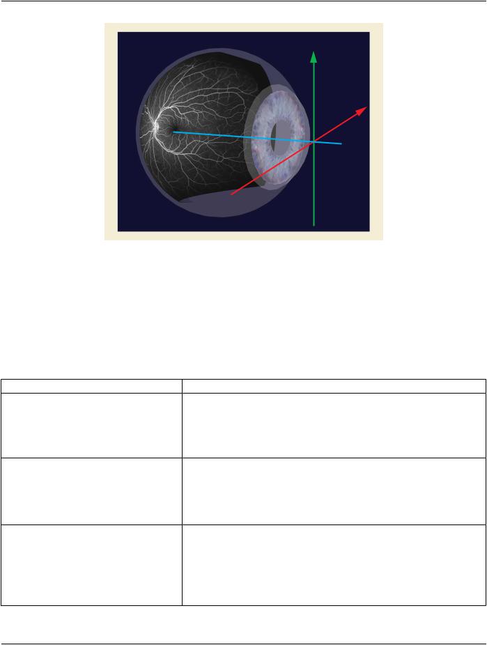
TheCornealVertexLocation(0046,0202)establishesthereferencepointforthecornealvertex,theoriginoftheOphthalmicCoordinate​ System.TheOphthalmicCoordinateSystemisusedastheFrameofReferencethatestablishesthespatialrelationshipforthecorneal​ vertex (i.e., used within corneal topography maps) for a set of Images within a Series. It also allows Images across multiple Series​ to share the same Frame Of Reference. The corneal vertex is the point located at the intersection of the patient's line of sight (visual​ axis) and the corneal surface. It is represented by the corneal light reflex when the cornea is illuminated coaxially with fixation.​

Note​

Since the criteria used to group images into a Series is application specific, it is possible for imaging applications to define​ multiple Series within a Study that share the same imaging space. Therefore the images with the same Frame of Reference​ UID (0020,0052) Attribute value share the same corneal vertex location within the patient's eye.​

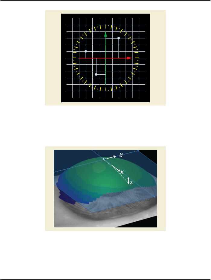
Figure C.8.30.3.1-3 illustrates the representation of corneal topography. The corneal vertex lies at the center of the rulers. Typical​ circular grids are 3, 5, 7, and 9 mm diameters centered on the vertex. The annotations in Figure C.8.30.3.1-3 are R, right; L, left; H​ = Head; F = Foot.​

H H

R L R L

F F

R L

Figure C.8.30.3.1-3. Representation of Corneal Topography​

Numerical position data shall use the Cartesian (i.e., two dimensional rectangular) coordinate system. The direction of the axes are​ determined by Patient Orientation (0020,0020), see Section C.7.6.1.1.1 for further explanation.​

Devices that internally capture data in polar coordinates will need to convert to Cartesian coordinates, see Figure C.8.30.3.1-4.​

- Standard -​

Page 1222​

DICOM PS3.3 2020a - Information Object Definitions​


90


120


60


Y

(2,3)


150


30


(-3,1)


180


X


0


210

(-1.5,-2.5)


330


240


300


270


Figure C.8.30.3.1-4. Sample Coordinate Data Points​

When using the 3 dimensional coordinates (X, Y, Z), the Z axis shall represent corneal elevation. Z shall be measured from the length​ of a vector normal to the plane that is normal to and intersects the corneal vertex at the intersection of the x, y, z, axes. It is shown​ in the diagram as "+" (0.0, 0.0, 0.0). The Z axis shall be positive towards the anterior direction of the eye; (i.e., it is a right-hand rule​ coordinate system. Thus the Z values (see Figure C.8.30.3.1-5 and Figure C.8.30.3.1-6) will be predominantly negative, as they are​ posterior to the plane of the corneal vertex.​

Figure C.8.30.3.1-5. Schematic of the 3-Dimensional Representation of Corneal Elevation​

- Standard -​

DICOM PS3.3 2020a - Information Object Definitions​

Page 1223​

Y

X

Z

FigureC.8.30.3.1-6.SchematicoftheOphthalmicCoordinateSystemofthe3-DimensionalRepresentation​

used in Wide Field Measurements​

C.8.31 Breast Projection Image Modules​

C.8.31.1 Enhanced Mammography Image Module​

Table C.8.31-1 specifies the Attributes that identify and describe general information about the Enhanced Mammography Image​ Module.​

Table C.8.31-1. Enhanced Mammography Image Module Attributes​

Attribute Name​

Tag​

Type​

Attribute Description​

Positioner Motion​

(0018,1500)​

1​ Describes the activity of the X-Ray Source during acquisition.​


See C.8.31.1.1 for Defined Terms.​

Positioner Type​

(0018,1508)​

1​

Enumerated Values:​


MAMMOGRAPHIC​

Content Qualification​

(0018,9004)​

1​

Enumerated Values:​


PRODUCT​


RESEARCH​


SERVICE​


See C.8.13.2.1.1 for further explanation.​

Acquisition DateTime​

(0008,002A)​

1​ Thedateandtimethattheacquisitionofdatathatresultedinthisimage​

started.​

Note​

The synchronization of this time with an external clock is​ specified in the Synchronization Module in Acquisition Time​ Synchronized (0018,1800).​

- Standard -​

Page 1224​

DICOM PS3.3 2020a - Information Object Definitions​

Attribute Name​

Tag​

Type​

Attribute Description​

Acquisition Duration​

(0018,9073)​

1​

The time in seconds needed for the compete acquisition.​


See C.7.6.16.2.2.1 for further explanation.​

Include Table C.8-71b “Digital X-Ray Detector Macro​


Attributes”​


KVP​

(0018,0060)​

1​

Average of the peak kilo voltage outputs of the X-Ray generator used​


for all frames.​

X-Ray Tube Current in mA​

(0018,9330)​

1C​

Average of the nominal X-Ray tube currents in milliamperes for all​


frames.​


RequiredifExposureinmAs(0018,9332)isnotpresent.Maybepresent​


otherwise.​

Exposure Time in ms​

(0018,9328)​

1C​

Total (cumulative) duration of X-Ray exposure for all acquired frames​


in milliseconds.​


RequiredifExposureinmAs(0018,9332)isnotpresent.Maybepresent​


otherwise.​

Exposure in mAs​

(0018,9332)​

1C​

The total (cumulative) exposure for all acquired frames expressed in​


mAs, for example calculated from Exposure Time and X-Ray Tube​


Current.​


Required if either Exposure Time in ms (0018,9328) or X-Ray Tube​


Current in mA (0018,9330) is not present. May be present otherwise.​

Focal Spot(s)​

(0018,1190)​

1​

Nominal focal spot size in mm used to acquire all frames.​

Anode Target Material​

(0018,1191)​

1​

The primary material in the anode of the X-Ray source.​


Defined Terms:​


TUNGSTEN​


MOLYBDENUM​


RHODIUM​

Body Part Thickness​

(0018,11A0)​

1​

The average thickness in mm of the body part examined when​


compressed, if compression has been applied during exposure.​

Compression Force​

(0018,11A2)​

1​

The compression force applied to the body part during exposure,​


measured in Newtons.​

Compression Pressure​

(0018,11A3)​

3​

The average compression pressure applied to the body part during​


exposure, calculated in kPa.​

CompressionContactArea​

(0018,11A5)​

3​

Theareaofthebodyparttowhichcompressionhasbeenappliedduring​


exposure, measured in mm2.​


Note​


Area information is useful in addition to the Compression​


Pressure (0018,11A3) and Compression Force (0018,11A2)​


in the event that unusual values are encountered.​

Paddle Description​

(0018,11A4)​

1​

Description of the compression paddle, if compression was applied to​


the body part during exposure.​

Exposure Control Mode​

(0018,7060)​

1​

Type of exposure control​


Defined Terms:​

AUTOMATIC​

MANUAL​

- Standard -​


DICOM PS3.3 2020a - Information Object Definitions​

Page 1225​

Attribute Name​

Tag​

Type​

Attribute Description​


Exposure Control Mode​

(0018,7062)​

1​

Text description of the mechanism of exposure control.​


Description​


May describe the number and type of exposure sensors or position of​


the sensitive area of the imaging detector.​


Patient Orientation​

(0020,0020)​

1C​

Patient direction of the rows and columns of the most representative​


frame.​


Required if View Code Sequence (0054,0220) has an Item value other​


than one representing a specimen image. May be present otherwise.​

Image Comments​

(0020,4000)​

3​

User-defined comments about the image.​


Samples per Pixel​

(0028,0002)​

1​

Number of samples (planes) in this image.​


Enumerated Values:​


1​


Photometric Interpretation​

(0028,0004)​

1​

Specifies the intended interpretation of the pixel data.​


Enumerated Values:​


MONOCHROME1​


MONOCHROME2​


Bits Allocated​

(0028,0100)​

1​

Numberofbitsallocatedforeachpixelsample.Eachsampleshallhave​


the same number of bits allocated.​


Enumerated Values:​


8​


16​


Bits Stored​

(0028,0101)​

1​

Number of bits stored for each pixel sample. Each sample shall have​


the same number of bits stored.​


Enumerated Values:​

8​

9​

10​

11​

12​

13​

14​

15​

16​

High Bit​

(0028,0102)​

1​ Most significant bit for pixel sample data. Each sample shall have the​


same high bit.​


Shall have an Enumerated Value of one less than the value of Bits​


Stored (0028,0101).​

Pixel Representation​

(0028,0103)​

1​ Data representation of the pixel samples. Each sample shall have the​


same pixel representation.​

Enumerated Values:​

0000H​unsigned integer​

- Standard -​