Материал: part03

Внимание! Если размещение файла нарушает Ваши авторские права, то обязательно сообщите нам


DICOM PS3.3 2020a - Information Object Definitions​

Page 1061​

Attribute Name​

Tag​

Type​

Attribute Description​


>Calibration Image​

(0050,0004)​

1​

Indicates whether a reference object (phantom) of known size is​


present in the frame and was used for calibration.​


Enumerated Values:​

YES​

NO​

Note​

Device is identified using the Device Module. See​

Section C.7.6.12.​

C.8.19.6.7 X-Ray Object Thickness Macro​

Table C.8.19.6-7 specifies the Attributes containing the X-Ray Object Thickness Group Macro.​

Table C.8.19.6-7. X-Ray Object Thickness Macro Attributes​

Attribute Name​

Tag​

Type​ Attribute Description​

Object Thickness Sequence​

(0018,9456)​

1​

Sequence containing object thickness for this frame.​


Only a single Item shall be included in this Sequence.​

>Calculated Anatomy​

(0018,9452)​

1​

The physical thickness in mm of the anatomic region of interest as​

Thickness​


specified in the Anatomic Region Sequence (0008,2218) in the​

direction of the center of the beam.​ Note​

Thevaluetakesinaccountthepositionrelativetoobjectand​ the X-Ray source - detector axis.​

C.8.19.6.8 X-Ray Frame Acquisition Macro​

Table C.8.19.6-8 specifies the Attributes containing the X-Ray Frame Acquisition Functional Group Macro.​

Table C.8.19.6-8. X-Ray Frame Acquisition Macro Attributes​

Attribute Name​

Tag​

Type​

Attribute Description​

Frame Acquisition Sequence​

(0018,9417)​

1​

Sequence containing the acquisition parameters for this frame.​


Only a single Item shall be included in this Sequence.​

>KVP​

(0018,0060)​

1​

Exact peak kilo voltage output of the X-Ray generator used for​


this frame.​

>X-Ray Tube Current in mA​

(0018,9330)​

1​

ExactNominalX-Raytubecurrentinmilliamperesappliedduring​


Acquisition Duration (0018,9220) for this frame.​

C.8.19.6.8.1 X-Ray Frame Acquisition Sequence Attributes​

These Attributes may only be used if the information is available on a frame-by-frame base. The average values for these Attributes​ ofallframesshallbestoredinthesameAttributeintheXA/XRFAcquisitionModuleorintheEnhancedMammographyImageModule.​

C.8.19.6.9 X-Ray Projection Pixel Calibration Macro​

Table C.8.19.6-9 specifies the Attributes of the X-Ray Projection Pixel Calibration Functional Group Macro.​

- Standard -​

Page 1062​ DICOM PS3.3 2020a - Information Object Definitions​

Table C.8.19.6-9. X-Ray Projection Pixel Calibration Macro Attributes​

Attribute Name​

Tag​

Type​

Attribute Description​

Projection Pixel​

(0018,9401)​

1​

A Sequence that describes the geometrical position of the patient relative to the​

Calibration Sequence​


equipment.​


Only a single Item shall be included in this Sequence.​

>Distance Object to​

(0018,9403)​

2​

Distance between the anatomic region of interest of observation and table top​

Table Top​


in mm.​


Note​


1.​This value is always positive, the object is assumed to be above​


the table.​


2.​The value of this Attribute is depending on the patient position on​


the tabletop (supine, left or right decubitus, etc.)​

>ObjectPixelSpacingin​ (0018,9404)​

1C​

Physicaldistancewithintheanatomicregionofinterestinthecenterofthebeam​

Center of Beam​


and perpendicular to the beam between the center of each pixel, specified by a​


numeric pair adjacent row spacing (delimiter) adjacent column spacing in mm.​


See Section C.8.19.6.9.2. See Section 10.7.1.3 for further explanation of the​


value order.​


Required if Distance Object to Table Top (0018,9403) is not empty.​


Note​


Thisvalueisprovidedbesidesthevaluesthataretheinputparameters​


of the calibration algorithm.​

>Table Height​

(0018,1130)​

1C​

The distance of the top of the patient table to the center of rotation of the source​


(i.e., the isocenter) in mm. A positive value indicates that the tabletop is below​


the isocenter.​


Note​


All the distances are measured perpendicular to the Table Top plane.​


Required if Image Type (0008,0008) Value 1 is ORIGINAL, may be present​


otherwise.​

>Beam Angle​

(0018,9449)​

1C​

The equipment related angle in degrees of the X-Ray beam relative to the​

perpendicular to the tabletop plane. An angle from 0 to +90 degrees indicates​ that the X-Ray source is below the table.​

The valid range is 0 to +180 degrees.​

Required if Image Type (0008,0008) Value 1 is ORIGINAL, may be present​ otherwise.​

C.8.19.6.9.1 Projection Calibration Method​

The X-Ray Projection Pixel Calibration Macro defines the Attributes needed to completely describe the specific inputs and results​ from projection image pixel calibration based on isocenter reference. The Attributes are provided to allow usage of calibration result​ as well as recalibration. Figure C.8.19.6-1 and Figure C.8.19.6-2 illustrate the relationship of the Attributes.​

In Figure C.8.19.6-1 and Figure C.8.19.6-2, the object of interest of size D (in mm) is projected on the stored image over a distance​ of #Px (in pixels). The pixel spacing on the stored image is called DPx. The "Source to Isocenter Distance" is called ISO. The "Source​ Image Receptor Distance" is called SID. The shortest distance from the tabletop plane to the Isocenter and to the object of interest​ are called respectively TH and TO. The angle between the X-Ray beam and the axis perpendicular to the tabletop plane is called​

- Standard -​

DICOM PS3.3 2020a - Information Object Definitions​

Page 1063​

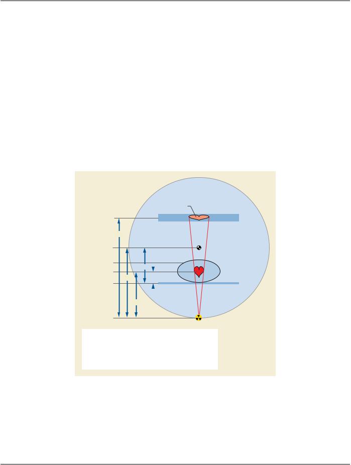
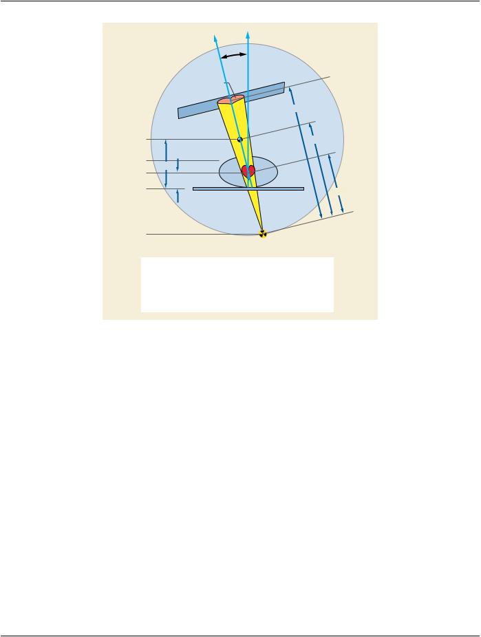
Beam Angle. Finally, the distance from the X-Ray source to the object of interest in the direction of the X-Ray beam is called SOD​ and is calculated from the other distances.​

DPx: Imager Pixel Spacing (0018,1164)​

ISO: Source Isocenter Distance (0018,9402)​

SID: Distance Source to Detector (0018,1110)​

TH: Table Height (0018,1130)​

TO: Distance Object to Table Top (0018,9403)​

Beam Angle: Beam Angle (0018,9449)​

Note​

The equipment related Beam Angle (0018,9449) Attribute shall be consistent with the patient oriented Positioner Primary​ Angle (0018,1510) and Positioner Secondary Angle (0018,1511) together with the patient orientation on the table specified​ in Patient Orientation Code Sequence (0054,0410) Attributes.​

Figure C.8.19.6-1 and Figure C.8.19.6-2 illustrate the usage of the Attributes under the conditions laid out above.​


#Px

Image Receptor


SID


Isocenter


Patient


TH


Object


D

ISO

TO

Patient Table


SOD


X-Ray Source


D = # Px * Px * SOD / SID


ISO : Source Isocenter Distance


SOD = ISO - ( TH - TO )


SID : Source Image Receptor Distance


SOD: Source Object Distance


TH : Table Height


TO : Distance Object Table Top


D: Distance in Object


#Px: Number Pixels


ΔPx: Imager Pixel Spacing


Figure C.8.19.6-1. Projection Calibration Without Angulation of the X-Ray Beam (Beam Angle = 0)​

- Standard -​

Page 1064​

DICOM PS3.3 2020a - Information Object Definitions​

Beam

Angle

Image Receptor


#Px


SID

Isocenter

ISO

Patient

TH


Object

D


TO

Patient

SOD

Table


X-Ray Source

D = # Px * Px * SOD / SID

ISO : Source Isocenter Distance

SOD = ISO - (TH-TO) / cos°(Beam Angle)

SID : Source Image Receptor Distance

SOD: Source Object Distance


TH : Table Height


TO : Distance Object Table Top


D: Distance in Object


#Px: Number Pixels


ΔPx: Imager Pixel Spacing


Figure C.8.19.6-2. Projection Calibration With Angulation of the X-Ray Beam (Beam Angle Not Equal to​ 0)​

C.8.19.6.9.2 Object Pixel Spacing in Center of Beam​

The value provided for Beam Angle (0018,9449) shall correspond to the other Attribute values within this Module and according to​ the mathematic terms listed in Section C.8.19.6.9.1.​

The terms listed will result in infinite result when used with 90-degree beam angles.​

It is outside the scope of this Standard to define reasonable limits for single input values in the above-mentioned terms, or to define​ the mathematical accuracy of applications using those terms.​

Note​

It may be reasonable to limit automatic calculations to a narrow range of +/- 60 degrees for Beam Angle and inform users​ about possible deviations in the calibration result when exceeding such range limits.​

C.8.19.6.10 X-Ray Positioner Macro​

Table C.8.19.6-10 specifies the Attributes of the X-Ray Positioner Functional Group Macro. If included into the Shared Functional​ GroupsSequence(5200,9229)noDYNAMICmotionwasperformedduringacquisition.IfincludedinthePer-frameFunctionalGroups​ Sequence (5200,9230) the indication of a DYNAMIC motion is given.​

- Standard -​

DICOM PS3.3 2020a - Information Object Definitions​ Page 1065​

Table C.8.19.6-10. X-Ray Positioner Macro Attributes​

Attribute Name​

Tag​

Type​

Attribute Description​

Positioner Position​

(0018,9405)​

1​

A Sequence that describes the geometrical position of the positioner.​

Sequence​


Only a single Item shall be included in this Sequence.​


>Positioner Primary Angle​ (0018,1510)​

1C​

Position of the X-Ray Image Intensifier about the patient from the RAO to​


LAO direction where movement from RAO to vertical is positive.​


See Section C.8.7.5.1.2.​


Required if Positioner Type (0018,1508) equals CARM.​

>Positioner Secondary​

(0018,1511)​

1C​

Position of the X-Ray Image Intensifier about the patient from the CAU to​

Angle​


CRA direction where movement from CAU to vertical is positive.​


See Section C.8.7.5.1.2​


Required if Positioner Type (0018,1508) equals CARM.​

>Column Angulation​

(0018,9447)​

1C​

Angle of the X-Ray beam in degree relative to an orthogonal axis to the​

(Patient)​


detector plane. Positive values indicate that the tilt is towards the head of​

the patient.​ Note​

1.​Thedetectorplaneisassumedtobeparalleltothetableplane​

2.​This Attribute differentiates form the Attribute Column​ Angulation(0018,1450)byusingthePatient-BasedCoordinate​ System instead of the Equipment-Based Coordinate System.​

Required if Positioner Type (0018,1508) equals COLUMN.​

C.8.19.6.11 X-Ray Table Position Macro​

Table C.8.19.6-11 specifies the Attributes of the X-Ray Table Position Functional Group Macro.​

Table C.8.19.6-11. X-Ray Table Position Macro Attributes​

Attribute Name​

Tag​

Type​

Attribute Description​

Table Position Sequence​

(0018,9406)​

1​ A Sequence that describes the geometrical position of the table top.​


Only a single Item shall be included in this Sequence.​

>Table Top Vertical Position​

(300A,0128)​

1​ Table Top Vertical position with respect to an arbitrary chosen​


reference by the equipment in (mm). Table motion downwards is​


positive​

>Table Top Longitudinal​

(300A,0129)​

1​ Table Top Longitudinal position with respect to an arbitrary chosen​

Position​


reference by the equipment in (mm). Table motion towards LAO is​


positive assuming that the patient is positioned supine and its head​


is in normal position.​

>Table Top Lateral Position​

(300A,012A)​

1​ Table Top Lateral position with respect to an arbitrary chosen​


reference by the equipment in (mm). Table motion towards CRA is​


positive assuming that the patient is positioned supine and its head​


is in normal position.​

>Table Horizontal Rotation​

(0018,9469)​

1​ Rotation of the table in the horizontal plane (clockwise when looking​

Angle​


from above the table).​

- Standard -​