Page 1066 |
DICOM PS3.3 2020a - Information Object Definitions |
Attribute Name |
Tag |
Type |
Attribute Description |
>Table Head Tilt Angle |
(0018,9470) |
1 |
Angle of the head-feet axis of the table in degrees relative to the |
|
|
|
horizontal plane. Positive values indicate that the head of the table is |
|
|
|
upwards. |
>Table Cradle Tilt Angle |
(0018,9471) |
1 |
Angle of the left-right axis of the table in degrees relative to the |
|
|
|
horizontal plane. Positive values indicate that the left of the table is |
|
|
|
upwards. |
C.8.19.6.11.1 X-Ray Table Position Macro Attribute Description
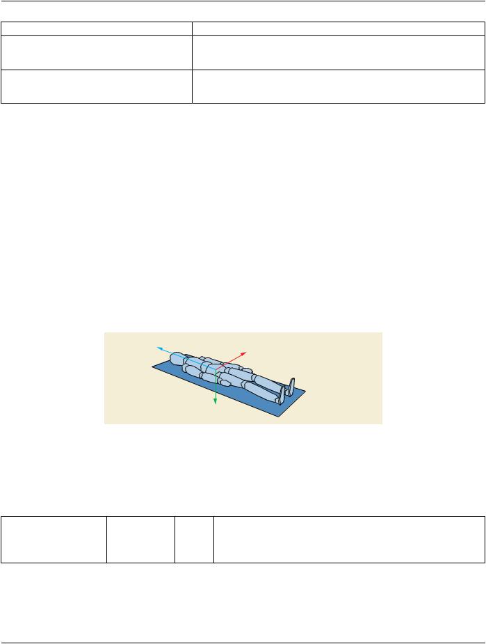
The Table Top Position Attributes of the Table Position Sequence (0018,9406) specify the geometrical position of the Table in the three spatial directions (i.e., Vertical, Longitudinal and Lateral) relative to the Table Top plane (see Figure C.8.19.6-3). The absolute reference point to which the Table positions are related is arbitrarily defined by the manufacturer.
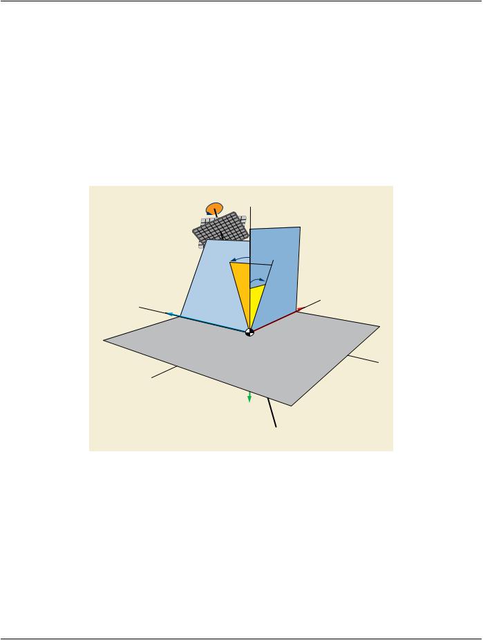
TheTableAngleAttributesoftheTablePositionSequence(0018,9406)specifytherotationandtiltoftheTableTopPlanewithrespect to a plane arbitrarily defined by the manufacturer (usually the horizontal plane).
The Table Top Position Attributes allow to describe the incremental translation of the Table top between frames of the same Multi- frame image, and between frames of different images, provided that the Table Angles are not modified between these frames.
When the table angles are modified between two frames, the Table Position Sequence (0018,9406) does not allow to characterize the relationship between the two table positions in an absolute reference coordinate system. For this purpose, the X-Ray Isocenter Reference System Macro has to be used.
Note
The incremental table translation may be used, in conjunction with the Positioner Position Sequence Attributes (0018,9405), for simple 2D-2D registration applications (object tracking, pixel shift…), assuming that the patient position is fixed on the table.Formorecomplexregistrationapplications,andinordertoproperlyhandlethechangesinthetableangles,itisrecom- mended to use the X-Ray Isocenter Reference System Macro Attributes.
+ Lateral Position
+ Longitudinal Position
+ Vertical Position |
Table Top Plane |
Figure C.8.19.6-3. Table Position Vectors
C.8.19.6.12 X-Ray Collimator Macro
Table C.8.19.6-12 specifies the Attributes of the X-Ray Collimator Functional Group Macro.
Table C.8.19.6-12. X-Ray Collimator Macro Attributes
Attribute Name |
Tag |
Type |
Attribute Description |
CollimatorShapeSequence |
(0018,9407) |
1 |
A Sequence that describes the collimator shape. |
|
|
|
Only a single Item shall be included in this Sequence. |


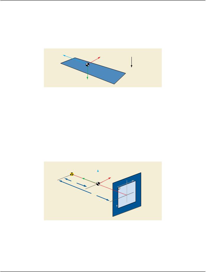
 X-Ray Source