Материал: part03

Внимание! Если размещение файла нарушает Ваши авторские права, то обязательно сообщите нам

DICOM PS3.3 2020a - Information Object Definitions​

Page 1071​

Ap3


Axis of Rotation


Ap3


TLHC


+Xp


+X


O


+Zp


+Z


+Y, +Yp


X-Ray Center Beam

Ap1 = Ap2 = 0

X-Ray Source


Figure C.8.19.6-7. Positioner Isocenter Detector Rotation Angle when Ap1 = 0 and Ap2 = 0​

C.8.19.6.13.1.3 Table Coordinate System​

The table coordinate system (Ot, Xt, Yt, Zt) is defined as follows:​

-Origin Ot, so-called Table Reference Point, is on the Table Top plane​

-+Xt direction to the TABLE LEFT​

-+Zt direction to the TABLE HEAD​

-+Yt direction to the TABLE DOWN​

The table coordinate system (Ot, Xt, Yt, Zt) is characterized, with respect to the Isocenter coordinate system (O, X, Y, Z), by a 3D​ translation and 3 angles describing the tilting and rotation:​

Table X Position to Isocenter (0018,9466) (so-called TX in Figure C.8.19.6-8) is defined as the translation of the Table Reference​ Point Ot with respect to the Isocenter Coordinate System in the X direction. Table motion toward +X is positive.​

Table Y Position to Isocenter (0018,9467) (so-called TY in Figure C.8.19.6-8) is defined as the translation of the Table Reference​ Point Ot with respect to the Isocenter Coordinate System in the Y direction. Table motion toward +Y is positive.​

Table Z Position to Isocenter (0018,9468) (so-called TZ in Figure C.8.19.6-8) is defined as the translation of the Table Reference​ Point Ot with respect to the Isocenter Coordinate System in the Z direction. Table motion toward +Z is positive.​

Note​

A translation of ( TX,TY,TZ ) = (0, 0, 0) means that the Table Reference Point Ot is at the System Isocenter.​

- Standard -​

Page 1072​

DICOM PS3.3 2020a - Information Object Definitions​

Table Horizontal Rotation Angle (so-called At1 in Figure C.8.19.6-9) is defined in the horizontal plane XZ, as the angle of the pro-​ jection of the +Zt axis in the XZ plane relative to the +Z axis. The axis of rotation of this angle is the vertical axis crossing the Table​ Reference Point Ot. Zero value is defined when the projection of +Zt in the XZ plane is equal to +Z. Angle from +Z to +X is positive.​ The valid range of this angle is -180 to +180 degrees.​

Table Head Tilt Angle (so-called At2 in Figure C.8.19.6-9) is defined in the vertical plane containing Zt (i.e., YZt), as the angle of the​ +Zt axis relative to the horizontal plane XZ. The axis of rotation of this angle is defined as the intersection between the horizontal​ plane XZ and the plane XtYt. Zero value is defined when +Zt is contained in the horizontal plane XZ. Angle from horizontal (plane XZ)​ to -Y direction (upwards) is positive, indicating that the head of the table is above the horizontal plane. The valid range of this angle​ is -45 to +45 degrees.​

Table Cradle Tilt Angle (so-called At3 in Figure C.8.19.6-9) is defined in the XtYt plane, as the angle of the +Xt axis relative to the​ intersection between the XtYt plane and the horizontal plane XZ. The axis of rotation of this angle is the axis Zt. Zero value is defined​ when +Xt is contained in the horizontal plane XZ. Angle from horizontal (plane XZ) to -Y direction (upwards) is positive, indicating that​ the left of the table is above the horizontal plane. The valid range of this angle is -45 to +45 degrees.​

Note​

The angles At1 , At2 and At3 are independent from any specific mechanical design of the table rotation axis defined by a​ manufacturer. In particular, they don't require the three rotation axis to cross on a single point. If a mechanical rotation axis​ does not cross the Table Reference Point Ot, a mechanical rotation around this axis will generate a change in one or more​ table angles as well as a translation of the Table Reference Point.​

+Z

+X

O

+Y

Z

(Tx, Ty, Tz)

Xt

Ot

Yt

Figure C.8.19.6-8. Table Translation with respect to the Isocenter Reference System​

- Standard -​

DICOM PS3.3 2020a - Information Object Definitions​

Page 1073​

XtZt plane

YZt plane

XtYt plane

+Z

Zt

At2

Xt

At1

Ot

XZ plane

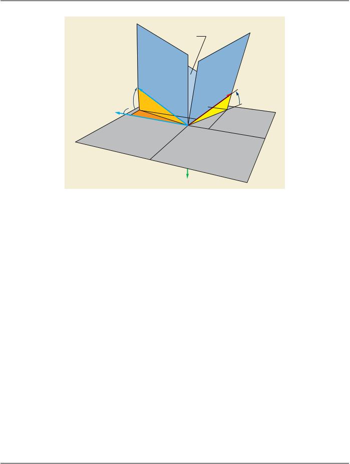
Figure C.8.19.6-9. Table Angulations with respect to the Isocenter Reference System​

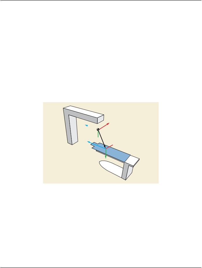
C.8.19.6.13.2 Relationship Patient Coordinate System​

The Isocenter Reference System Attributes allow expressing the positioner angulations (i.e., X-Ray Center Beam direction) as a​ vector in the table coordinate system. If the relationship between the X-Ray table and the patient is known, it is possible to express​ any vector of the table coordinate system as a direction in the patient.​

Therefore, the Isocenter Reference System Attributes allow calculating the positioner angulations in the Patient-Based Coordinate​ System if the following Attributes are present:​

•​Patient Orientation Code Sequence (0054,0410)​

•​Patient Orientation Modifier Code Sequence (0054,0412)​

Further, the Isocenter Reference System Attributes allow calculating the patient anatomical directions (i.e., left, right, head, feet, an-​ terior, posterior) of the rows and columns of the stored image, if the following Attributes are present:​

•​Patient Orientation Code Sequence (0054,0410)​

•​Patient Orientation Modifier Code Sequence (0054,0412)​

•​Field of View Rotation (0018,7032)​

•​Field of View Horizontal Flip (0018,7034)​

For registration purposes, a given point fixed in the patient (object of interest) that is defined in the table coordinate system can be​ expressed as row and column coordinates of the stored image if the relationship between the positioner coordinate system and the​ stored image is fully characterized. Therefore, the Isocenter Reference System Attributes allow calculating the projection of a point​ of the patient as row and column coordinates of the stored image, if the following Attributes are present:​

•​Frame of Reference UID (0020,0052) and must be equal for all images involved in the registration​

•​Field of View Rotation (0018,7032)​

•​Field of View Horizontal Flip (0018,7034)​

- Standard -​

Page 1074​

DICOM PS3.3 2020a - Information Object Definitions​

•​Imager Pixel Spacing (0018,1164)​ •​Distance Source to Isocenter (0018,9402)​ •​Distance Source to Detector (0018,1110)​

In addition for a system equipped with a digit al detector the following Attributes need to be present:​ •​Detector Element Spacing (0018,7022)​

•​Field of view Origin (0018,7030)​ •​Position of Isocenter Projection (0018,9430)​

C.8.19.6.14 X-Ray Geometry Macro​

Table C.8.19.6-14 specifies the Attributes containing the X-Ray Geometry Functional Group Macro.​

Table C.8.19.6-14. X-Ray Geometry Macro Attributes​

Attribute Name​

Tag​

Type​

Attribute Description​

X-Ray Geometry Sequence​

(0018,9476)​

1​ Sequence containing the geometric properties for this frame.​


Only a single Item shall be included in this Sequence.​

>Distance Source to Isocenter​

(0018,9402)​

1​ Distance from source to isocenter in mm.​

>Distance Source to Detector​

(0018,1110)​

1​ Distance from source to receptor plane perpendicular to the​


receptor plane in mm.​

Note​

ThisvalueistraditionallyreferredtoasSourceImage​

Receptor Distance (SID).​

C.8.19.7 XA/XRF Multi-frame Presentation Module​

Table C.8.19.7-1 specifies the Attributes of a XA/XRF Multi-frame Presentation Module.​

Table C.8.19.7-1. XA/XRF Multi-frame Presentation Module Attributes​

Attribute Name​

Tag​

Type​

Attribute Description​

Preferred Playback​

(0018,1244)​

3​ Describes the preferred playback sequencing for a multi-frame image.​

Sequencing​


Enumerated Values:​


0​Looping (1,2…n,1,2,…n,1,2,….n,…)​


1​Sweeping (1,2,…n,n -1,…2,1,2,…n,…)​

Frame Display Sequence​

(0008,9458)​

3​ Sequence that specifies the display frame rate of a selected set of frames.​


TheItemsareorderedinincreasingframenumber.Therangeoftheframes​


may not overlap and the ranges shall be adjacent.​


One or more Items are permitted in this Sequence.​

>Start Trim​

(0008,2142)​

1​ The Frame Number of the first frame of the set of frames to be displayed​


in this Item.​

>Stop Trim​

(0008,2143)​

1​ The Frame Number of the last frame of the set of frames to be displayed​


in this Item.​

- Standard -​


DICOM PS3.3 2020a - Information Object Definitions​

Page 1075​

Attribute Name​

Tag​

Type​

Attribute Description​


>Skip Frame Range Flag​

(0008,9460)​

1​

A flag indicating that the range of frames in this Item may be skipped.​


Defined Terms:​


DISPLAY​


SKIP​


>Recommended Display​

(0008,9459)​

1​

Recommended rate at which the frames of this Item should be displayed​

Frame Rate in Float​


in frames/second.​


>Recommended Viewing​

(0028,1090)​

2​

Specifies the recommended viewing protocol(s).​


Mode​


When this Attribute is present with a value, this value shall override the​


value of Recommended Viewing Mode (0028,1090) specified in the Mask​


Module.​


Defined Terms:​


SUB​subtraction with mask images​


NAT​native viewing of image as stored​


Note​


If an implementation does not recognize the Defined Term for​


Recommended Viewing Mode (0028,1090), reverting to native​


display mode is recommended.​


>Display Filter Percentage​

(0028,9411)​

2​

Edgeenhancementfilterpercentagethatisrecommendedbythepixeldata​


creator as filter presetting for display purposes. The value of 100​


correspondstothemaximumfilterstrengththatcanbeappliedbyaspecific​


application displaying the image.​


>MaskVisibilityPercentage​

(0028,9478)​

1C​

The percentage of visibility of the mask frame during a subtracted display.​

A value of 0 corresponds to subtracted display, a value of 100 corresponds​ to un-subtracted display (native). See Section C.8.19.7.1.​

Note​

The value of 100 is equivalent to Recommended Viewing Mode​ (0028,1090) having a value of NAT.​

Required if Recommended Viewing Mode (0028,1090) equals SUB.​

C.8.19.7.1 Multi-frame Presentation Attributes​

C.8.19.7.1.1 Mask Visibility Percentage (Informative)​

An example of the usage of the Mask Visibility Percentage (0028,9478) Attribute is illustrated below.​

Assume that Psub is the output pixel level of a subtracted frame, its calculation can be expressed as followed:​

Pcontrast: Pixel level of the contrast frame in the logarithmic domain​

Pmask: Pixel level of the mask frame in the logarithmic domain​

X: Mask Visibility Percentage (0028,9478): 0 <= X <= 100​

Psub = Pcontrast- (1- X/100) * Pmask​

C.8.20 Segmentation​

This section describes the specific Modules for the Segmentation IOD.​

- Standard -​