Материал: part03

Внимание! Если размещение файла нарушает Ваши авторские права, то обязательно сообщите нам

Page 826​

DICOM PS3.3 2020a - Information Object Definitions​

Control Point 1: All applicable treatment parameters defined, Cumulative Meterset Weight = 30.0 Nominal Energy: 200 Scan Spot​ Position Map: -40, -35, -40, -30 (Positions for 1st segment) Scan Spot Meterset Weight:0.0, 0.0, 0.0, … (All values are 0.0, because​ Meterset Weight difference between Control Point 1 and 2 is 0.0)​

Control Point 2: All applicable treatment parameters defined, Cumulative Meterset Weight = 30.0 Nominal Energy: 180 Scan Spot​ Position Map: -55, -40, -55, -35, (Positions for 2nd segment) Spot Meterset Weight: 0.7, 0.8, 1.5 (Values add up to Meterset difference​ between Control Points 2 and 3)​

Control Point 3: All applicable treatment parameters defined, Cumulative Meterset Weight = 70.0 Nominal Energy: 180 Scan Spot​ Position Map: -55, -40, -55, -35, (Positions for 2nd segment) Spot Meterset Weight: 0.0, 0.0, 0.0, (All values are 0.0, because there​ is no following control point (end of sequence).​

C.8.8.25.8 Scan Spot Maps​

The Scan Spot Position Map (300A,0394) and Scan Spot Meterset Weights (300A,0396) shall be used as follows.​

The following specifies for each value of Modulated Scan Mode Type (300A,0309) the definition of the map which is included in the​ Control Point 1 having Cumulative Meterset Weight (300A,0134) = 20, followed by a Control Point 2 having Cumulative Meterset​ Weight(300A,0134) = 20.​

If Modulated Scan Mode Type (300A,0309) is STATIONARY or LEAPING:​

Position (X,Y)​

(1.0, 2.0)​

(3.0, 2.0)​

(5.0, 2.0)​

(7.0, 2.0)​

(9.0, 2.0)​

Meterset Weights​

5​

4​

6​

2​

3​

Delivery Description:​


•​The beam is positioned at Scan Spot Position (1.0, 2.0).​


•​The beam is delivered with a Cumulative Meterset Weight of 5.​


•​The beam is switched off or quickly moved and positioned at Scan Spot Position (3.0, 2.0).​


•​The beam is delivered with a Cumulative Meterset Weight of 4.​


•​The beam is switched off or quickly moved and positioned at Scan Spot Position (5.0, 2.0).​


•​The beam is delivered with a Cumulative Meterset Weight of 6.​


•​The beam is switched off or quickly moved and positioned at Scan Spot Position (7.0, 2.0).​


•​The beam is delivered with a Cumulative Meterset Weight of 2.​


•​The beam is switched off or quickly moved and positioned at Scan Spot Position (9.0, 2.0).​


•​The beam is delivered with a Cumulative Meterset Weight of 3.​


If Modulated Scan Mode Type (300A,0309) is LINEAR:​


Position (X,Y)​

(1.0, 2.0)​

(3.0, 2.0)​

(5.0, 2.0)​

(7.0, 2.0)​

(9.0, 2.0)​

Meterset Weights​

0​

4​

6​

7​

3​

Delivery Description:​

•​The beam is positioned at Scan Spot Position (1,.0 2.0).​

•​The beam is continuously delivered with a Cumulative Meterset Weight of 4, while being moved from Scan Spot Position (1.0, 2.0)​ to Scan Spot Position (3.0, 2.0).​

•​The beam is continuously delivered with a Cumulative Meterset Weight of 6, while being moved from Scan Spot Position (3.0, 2.0)​ to Scan Spot Position (5.0, 2.0).​

- Standard -​

DICOM PS3.3 2020a - Information Object Definitions​

Page 827​

•​The beam is continuously delivered with a Cumulative Meterset Weight of 7, while being moved from Scan Spot Position (5.0, 2.0)​ to Scan Spot Position (7.0, 2.0).​

•​The beam is continuously delivered with a Cumulative Meterset Weight of 3, while being moved from Scan Spot Position (7.0, 2.0)​ to Scan Spot Position (9.0, 2.0).​

If Modulated Scan Mode Type (300A,0309) is MIXED:​


Position (X,Y)​

(1.0, 2.0)​

(1.0, 2.0)​

(3.0, 2.0)​

(5.0, 2.0)​

(5.0, 2.0)​

(7.0, 2.0)​

(7.0, 2.0)​

Meterset Weights​

0​

4​

6​

5​

2​

0​

3​

Delivery Description:​

•​The beam is positioned at Scan Spot Position (1.0, 2.0).​

•​The beam is delivered with a Cumulative Meterset Weight of 4 while staying at Scan Spot Position (1.0, 2.0).​

•​The beam is continuously delivered with a Cumulative Meterset Weight of 6, while being moved from Scan Spot Position (1.0, 2.0)​ to Scan Spot Position (3.0, 2.0).​

•​The beam is continuously delivered with a Cumulative Meterset Weight of 5, while being moved from Scan Spot Position (3.0, 2.0)​ to Scan Spot Position (5.0, 2.0).​

•​The beam is delivered with a Cumulative Meterset Weight of 2 while staying at Scan Spot Position (5.0, 2.0).​ •​The beam is switched off or quickly moved and positioned at Scan Spot Position (7.0, 2.0).​

•​The beam is delivered with a Cumulative Meterset Weight of 3 while staying at Scan Spot Position (7.0, 2.0).​

C.8.8.25.9 Depth Dose Parameters Sequence Attributes​

Some delivery systems determine the settings of the range shifter (or beam energy) and range modulators internally based upon​ clinical parameters.​

The Attributes mentioned in this section represent those clinical parameters.​

When the Depth Dose Parameters Sequence (300A,0505) is present, those specifications have precedence over the definitions of​ the Range Shifters defined in Range Shifter Settings Sequence (300A,0360) and the Range Modulator defined in Range Modulator​ Settings Sequence (300A,0380).​

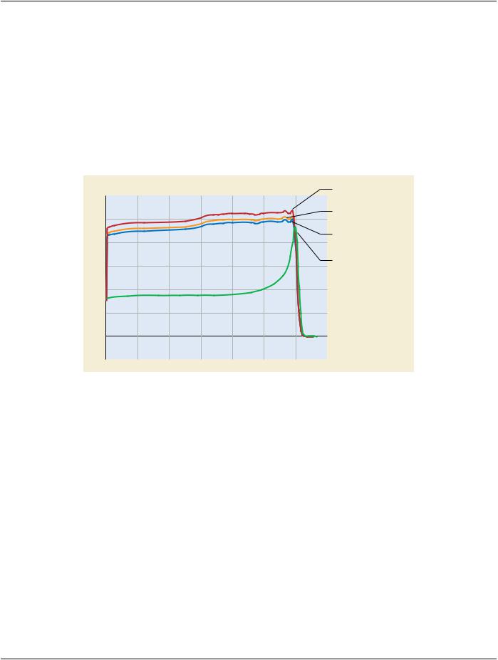
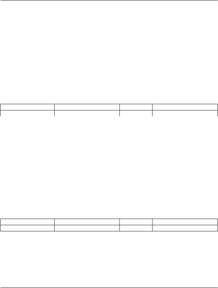
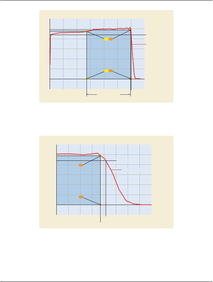
The following three figures explain the use of the Range Modulated Region Attributes.​

Figure C.8.8.25.9-1 shows an example of those Attributes with the following values:​

Nominal Range Modulated Region Depths (300A,0504) = 147\298​

Reference Dose Definition (300A,0512) = CENTER​

Distal Depth (300A,0502) = 301​

Distal Depth Fraction (300A,0501) = 0.9​

Nominal Range Modulation Fractions (300A,0503) = 0.95\0.98​

- Standard -​

Page 828​

DICOM PS3.3 2020a - Information Object Definitions​

Dose Ratio (%)


Depth Dose


120


100


Distal Depth Fraction

80


(300A,0503)


Nominal Range Modulation Fractions


Reference Dose Definition


60


40


20


Nominal Range Modulated Region Depths


(300A,0504)


0


range (mm)

0

50

100

150

200

250

300

350

-20


Distal Depth


Range Modulated Region


Proximal Limit


Distal Limit


Figure C.8.8.25.9-1. Attributes specifying a depth dose distribution parameters in case of Reference​ Dose Definition (300A,0512) = CENTER​

Figure C.8.8.25.9-2 is an expansion of the steep-gradient part of the depth dose curve for better readability of the parameters annot-​ ating this part.​

Dose Ratio (%)

Depth Dose

120


100


Distal Depth Fraction

80

(300A,0503)


Nominal Range Modulation Fractions

Reference Dose Definition


60


40

20 Nominal Range Modulated Region Depths

(300A,0504)

0


range (mm)

280

285

290

295

300

305

310

315

320

-20

Distal Depth

Range Modulated Region

Distal Limit

Figure C.8.8.25.9-2. Attributes specifying a generic depth dose distribution. Abscissa expanded near​ distal edge of dose distribution.​

Defined Terms for Reference Dose Definition (300A,0512):​

HIGHEST​The maximum dose for the highest energy of the non-range modulated component is used for determining the fractions.​ MAXIMUM​The maximum dose of the range modulated depth dose distribution is used for determining the fractions.​

CENTER​The dose measured at the center of the range modulated region of the depth dose distribution is used for determining the​ fractions.​

- Standard -​

DICOM PS3.3 2020a - Information Object Definitions​

Page 829​

Figure C.8.8.25.9-3 shows the usage of the Defined Terms of Reference Dose Definition (300A,0512).​

In Figure C.8.8.25.9-3, the modulated region is defined the same as in Figure C.8.8.25.9-1:​

•​Nominal Range Modulated Region Depths (300A,0504) = (147\298)​

In this example, the 100% reference level for the dose definition is determined for the Defined Terms specified in Reference Dose​ Definition (300A,0512) as follows:​

HIGHEST​The maximum dose for the highest energy of the non-range modulated component is located at 304 mm and used for​ determining the fractions.​

MAXIMUM​The maximum dose of the range modulated depth dose distribution is located at 300 mm and used for determining the​ fractions.​

CENTER​The dose measured at 220 mm depth at the center of the range modulated region of the depth dose distribution is used​ for determining the fractions.​

Dose Ratio (%)

Depth Dose

MAXIMUM: normalized to the

120


maximum dose of the range


modulated depth dose distribution


CENTER: normalized to the dose

100


at the center of the range


modulated region


HIGHEST: normalized to the

80


maximum dose of the depth dose


distribution of the highest energy


Non-Range Modulated component

Non-Range Modulated

60


40


20


0


range (mm)

0

50

100

150

200

250

300

350

-20


Figure C.8.8.25.9-3. Representation of the different Reference Dose Definition (300A,0512) using the​ range modulated depth dose distribution or highest energy component depth dose distribution.​

C.8.8.25.10 Isocenter to Accessory Distance​

Snout Position (300A,030D) is defined at the Control Point level and can therefore vary during the beam, causing all the accessories​ attached to the Snout (Applicator, Block, Compensator, etc.) to move as well.​

For each accessory which is attached to the Snout and has its distance to isocenter defined at the Beam level (such as Isocenter to​ BeamLimitingDeviceDistance(300A,00BB),IsocentertoCompensatorTrayDistance(300A,02E4),IsocentertoBlockTrayDistance​ (300A,00F7) ), the prescribed physical position of the accessory is defined at the first Control Point.​

This is consistent with the approach used for Beam Limiting Device Boundaries and Positions (see Section C.8.8.25.3 Leaf Position​ Boundaries).​

For accessories which are attached to the Snout whose distance is defined at the Control Point level, such as Isocenter to Lateral​ Spreading Device Distance (300A,0374) and Isocenter to Range Modulator Distance (300A,038A), and are attached to the Snout,​ both the Snout Position (300A,030D) and the accessory distance must change by the same amount.​

C.8.8.25.11 Block and Compensator Data​

Similarly to Section C.8.8.25.3, in the case where Snout Position (300A,030D) changes between control points, the scaling factor to​ be used to convert from DICOM data defined at the isocenter plane (such as Block Data (300A,0106) and Isocenter to Compensator​ Distances (300A,02E6) ) to the physical dimension of the accessories is purely based on the Isocenter to Compensator Tray Distance​

- Standard -​

Page 830​

DICOM PS3.3 2020a - Information Object Definitions​

(300A,02E4) and Isocenter to Compensator Distances (300A,02E6) defined at the beam level and should not take into account the​ possible effect of Snout Position (300A,030D) changes between Control Points.​

C.8.8.26 RT Ion Beams Session Record Module​

TableC.8.8.26-1specifiestheAttributesthatdescribethemeasuredandrecordedsettingsacquiredduringIonRadiationTreatments.​

Table C.8.8.26-1. RT Ion Beams Session Record Module Attributes​

Attribute Name​

Tag​

Type​

Description​

Referenced Fraction Group​

(300C,0022)​

3​

Identifier of fraction group within referenced RT Ion Plan.​

Number​


Number of Fractions​

(300A,0078)​

2​

Total number of treatments (fractions) planned for current fraction group.​

Planned​


Primary Dosimeter Unit​

(300A,00B3)​

1​

Measurement unit of the machine dosimeter.​


Enumerated Values:​


MU​Monitor Units​


NP​Number of Particles​

TreatmentSessionIonBeam​

(3008,0021)​

1​

Sequenceofsetupand/ortreatmentbeamsadministeredduringtreatment​

Sequence​


session.​


One or more Items shall be included in this Sequence.​

>Referenced Beam Number​

(300C,0006)​

1​

References Beam specified by Beam Number (300A,00C0) in Ion Beam​


Sequence (300A,03A2) in RT Ion Beams Module within the referenced​


RT Ion Plan.​

>Beam Name​

(300A,00C2)​

1​

User-defined name for Beam. See Section C.8.8.25.1.​

>Beam Description​

(300A,00C3)​

3​

User-defined description for Beam. See Section C.8.8.25.1.​

>Beam Type​

(300A,00C4)​

1​

Motion characteristic of Beam.​


Enumerated Values:​


STATIC​ all beam parameters remain unchanged during delivery​


DYNAMIC​one or more beam parameters changes during delivery​

>Radiation Type​

(300A,00C6)​

1​

Particle type of Beam.​


Defined Terms:​


PHOTON​


PROTON​


ION​

>Radiation Mass Number​

(300A,0302)​

1C​

Mass number of radiation. Required if Radiation Type (300A,00C6) is​


ION​

>Radiation Atomic Number​

(300A,0304)​

1C​

Atomic number of radiation. Required if Radiation Type (300A,00C6) is​


ION​

>Radiation Charge State​

(300A,0306)​

1C​

Chargestateofradiation.RequiredifRadiationType(300A,00C6)isION​

- Standard -​