Материал: part03

Внимание! Если размещение файла нарушает Ваши авторские права, то обязательно сообщите нам

DICOM PS3.3 2020a - Information Object Definitions​

Page 821​

a.​Snout positioning:​

The mounting positions as depicted in the drawing are only examples. As the block tray does not really exist in most of the cases,​ it is only used as a reference position. As some machines use the downstream face of the block as a reference position for their​ snout positioning, it could make sense to define for example that the block mounting position must be SOURCE_SIDE. In this​ case, one uses the downstream face of the block as the reference position, which is the same side as used by the machine. This​ definition is always independent of the actual thickness of the block. The Isocenter-Block Distance is defined and the machine​ can deduce the position of the snout from this value.​

b.​Scaling of block/compensator data for manufacturing​

The Isocenter position is always used as the reference position for all distances measured 'from isocenter'. Real size block and​ compensatormanufacturingshouldbebasedonthedistancefromtheVirtualSource(X/Y)tothedevice,i.e.,VirtualSourceToDevi-​ ceDistance = VirtualSAD - IsocenterToDeviceDistance.​

C.8.8.25.5 Range Shifter and Lateral Spreading Device Settings​

The Range Shifter and Lateral Spreading Device Settings Attributes are used to capture machine specific values related to these​ devices. For example, some machines may specify the Range Shifter setting as the desired Water-Equivalent Thickness (in mm).​ Others contain a series of interchangeable plates, whose position in or out of the beam is specified by a series of ones and zeros​ (i.e., 100010 would specify that plates #1 and #5 are in the beam). If the device does not use a specific setting, but rather is defined​ by the ID, then the Enumerated Values IN/OUT shall be used for the setting.​

C.8.8.25.6 Coordinate Systems​

Where explicitly specified, the coordinate systems defined by IEC 61217 shall be applied, with the exception of the IEC PATIENT​ Coordinate System.​

In addition, the following sections define the coordinate systems to be used in situations where IEC 61217 coordinate systems are​ not applicable. No other coordinate systems shall be used.​

C.8.8.25.6.1 Fixed Beam Line​

The direction of fixed beam-line can be described as a gantry system, provided that the position of the (virtual) gantry bearing is​ defined. The relation between their patient support coordinate system axes and the choice of the 'gantry' angle, e.g., 90 or 270 deg,​ shallbeconsistentwithastandardgantrycoordinatesystem.AllcoordinatesystemsderivedfromtheIECGANTRYcoordinatesystem​ (BEAM LIMITING DEVICE, WEDGE, X-RAY IMAGE RECEPTOR) automatically follow in the same way as defined in a 'real' gantry​ system.​

The IEC PATIENT SUPPORT system is linked to the IEC GANTRY coordinate system through its common parent system, the IEC​ FIXED coordinate system. The Y-axis of IEC GANTRY points towards the (virtual) gantry bearing. The Y-axis of the IEC FIXED co-​ ordinate system has to point in the same direction. Z-axis in IEC FIXED coordinate system is always pointing upwards. With Y and​ Z-axes defined, the X-axis of IEC FIXED is also given.​

Figure C.8.8.25-2a and Figure C.8.8.25-2b show IEC FIXED (F), GANTRY (G) and PATIENT SUPPORT (S) coordinate systems for​ a horizontal fixed beam-line.​

- Standard -​

Page 822​

DICOM PS3.3 2020a - Information Object Definitions​

Zf

Φg = 90º

Y

f

Yf = Yg

Xf

Xf = Zg

-Xg

Figure C.8.8.25-2a. Fixed Beam Line - View Along IEC FIXED Y-axis​

Zs =

s

Xf

Figure C.8.8.25-2b. Fixed Beam Line - View From Top (Along IEC FIXED Z-axis)​

C.8.8.25.6.2 Table Top Pitch and Table Top Roll​

For further information, see Section C.8.8.14.12.​

C.8.8.25.6.3 Seated Treatments​

RTIonPlancontainsanAttributePatientSupportType(300A,0350),whichcanbeCHAIRorTABLE.ThepatientsupporttypeCHAIR​ does not change the coordinate axes of the patient support coordinate systems relative to their parent systems. It is more an Attribute​ of the type like the patient position in imaging (i.e., HFS, HFP, …).​

The orientation of the treatment chair shall be defined with the chair positioned in such way, that the patient looks towards the gantry​ bearing (or along the Y axis of the IEC FIXED system) if all angles, especially IEC PATIENT SUPPORT angle are 0°. All other para-​ meters follow straight forward, once this definition is accepted. i.e., chair rotation is a rotation of IEC PATIENT SUPPORT coordinate​

- Standard -​

DICOM PS3.3 2020a - Information Object Definitions​

Page 823​

system; a backward tilt of the chair is a positive rotation of the PITCHED TABLE TOP coordinate system. A translation of the chair is​ a translation of the IEC TABLE TOP system.​

The roll angle is typically 0º.​

For a seated treatment on a horizontal beam-line, the following angles are therefore defined:If IEC GANTRY angle is 90º (270º), IEC​ PATIENT SUPPORT angle is 270º (90º) for the position where the patient looks into the beam port.​

C.8.8.25.6.4 Ocular Treatments​

C.8.8.25.6.4.1 Gantry Beam Line​

Eye treatments on the gantry shall use all existing IEC coordinate systems with their standard definition. This applies especially to​ IEC BEAM LIMITING DEVICE, IEC WEDGE FILTER, IEC X-RAY IMAGE RECEPTOR.​

IEC PATIENT SUPPORT, and IEC TABLE TOP coordinate systems are defined as above. Additionally, a rotation of the head fixation​ device is possible. The Head Fixation Angle (300A,0148) shall be defined as the angle of the head fixation device with respect to the​ TABLE TOP coordinate system. Positive head fixation angle is in the same direction as positive PATIENT SUPPORT pitch, i.e.,​ backwards.​

Proton eye treatments require an additional coordinate system for the placement of the fixation light. Since it is usually mounted onto​ the beam port the 'natural' coordinate system for devices mounted there is the IEC BEAM LIMITING DEVICE coordinate system. The​ angles for the fixation light positions shall therefore be defined as follows:​

Rotation of the fixation light about the IEC BEAM LIMITING DEVICE Z-axis (Zb) is defined as Azimuthal Angle. The Azimuthal Angle​ is equal to 0° when the fixation light is positioned on the axis Xb of the IEC BEAM LIMITING DEVICE coordinate system. An increase​ in the value of the Azimuthal Angle corresponds to clockwise rotation of the fixation light as view along the axis Zb towards the virtual​ source.​

The polar angle is always positive and defined as the angle between IEC BEAM LIMITING DEVICE Z-axis and the line connecting​ isocenter with the fixation light position.​

Proton eye treatments require the wedge thin edge position as one additional. The wedge thin edge position allows the specification​ ofawedge,whichdoesnotcoverthefullopenfield.Thewedgethinedgepositionispositive,ifthewedgedoesnotcovertheisocenter​ position and negative, if it does cover.​

Figure C.8.8.25-5 and Figure C.8.8.25-6 show the angles and Attributes as described above.​

- Standard -​

Page 824​

DICOM PS3.3 2020a - Information Object Definitions​


Yb

θw

θLight


L

Xb


dw


Wedge

L

Fixation Light

Yb

θ

Fixation light azimuthal angle


Light


Xb, Zb

axes of the IEC BEAM LIMITING DEVICE coordinate system


dw

Wedge thin edge position

Xb

θ

Wedge orientation angle


Zb

w


Figure C.8.8.25-5. Patient's eye view​

Yb


L

ΨLight

dw

Zb

Virtual Source


Position

Wedge


Yb

L Fixation Light

ΨFixation light polar angle

Light


Yb, Zb

axes of the IEC BEAM LIMITING DEVICE coordinate system

Xb

dw


Wedge thin edge position

Zb

Figure C.8.8.25-6. Lateral view along the positive axis Xb​

C.8.8.25.6.4.2 Fixed Beam Line​

The coordinate systems for the treatment chair are defined above and shall also be applied to seated eye treatments.​

- Standard -​

DICOM PS3.3 2020a - Information Object Definitions​

Page 825​

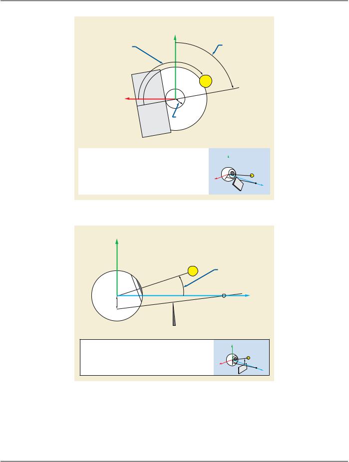
In this case, it is recommended that a beam limiting device angle of 90º be formally applied (provided the gantry angle is defined to​ be 90º (and not 270º). This results in the same coordinates of the fixation light and wedge relative to the patient as in the treatment​ situation with the patient lying on the table.​

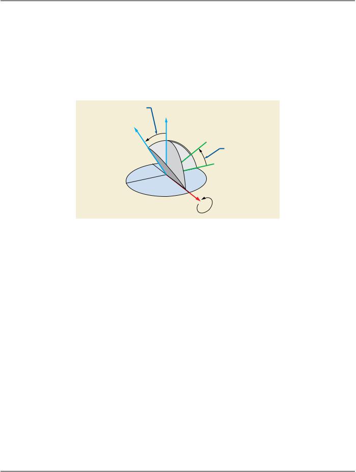
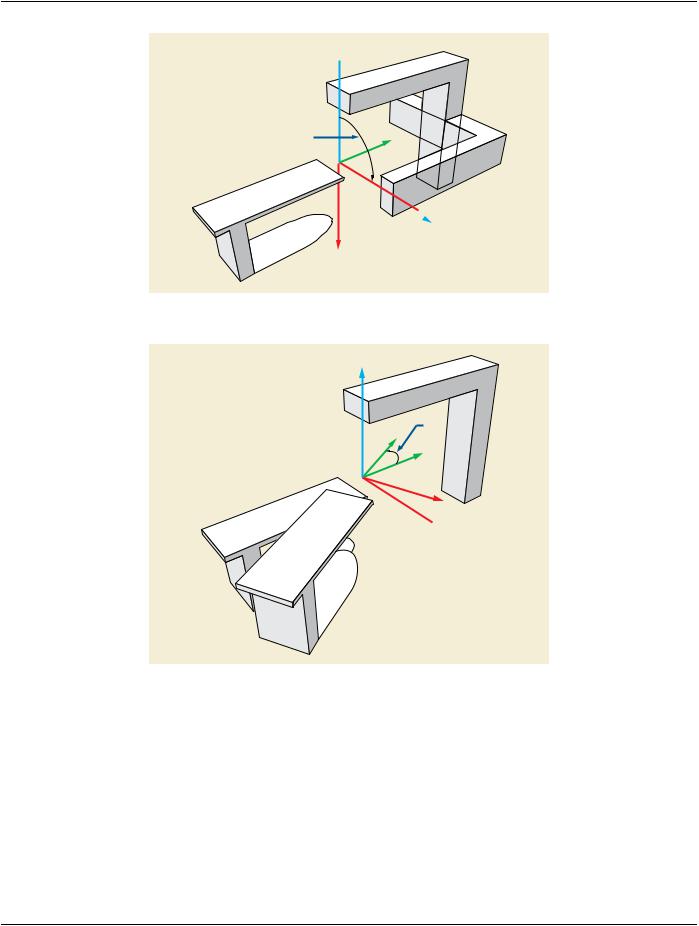
C.8.8.25.6.5 Gantry Pitch Angle​

The Gantry Pitch Angle is not defined in IEC 61217. This angle is defined in the DICOM Standard in a way compatible with the current​ notion of IEC by introducing it as rotation of the IEC GANTRY System as indicated below.​

The Gantry Pitch Angle is defined as the rotation of the coordinate axes Yg, Zg about axis Xg by an angle ψg; See Figure C.8.8.25-​ 7. An increase in the value of angle ψg corresponds to the clockwise rotation as viewed from the isocenter along the positive Xg axis​

Ψg Zg

Z’g

Y’g

Ψg

Yg

Xg - Yg Plane

Xg

Figure C.8.8.25-7. Gantry Pitch Angle​

C.8.8.25.7 Ion Control Point Sequence​

The control point sequence for RT Ion Beams is defined using the same rule set as in the RT Beams Module (see Section C.8.8.14.5).​ Specifically, the following rules apply:​

•​All parameters that change at any control point of a given beam shall be specified explicitly at all control points (including those​ preceding the change).​

•​All parameters of an irradiation segment (i.e., with values of the Cumulative Meterset Weight (300A,0134) different at the beginning​ and at the end of the segment) shall therefore be specified in 2 separate control points denoting the beginning and at the end of​ this segment. Each irradiation segment is therefore represented by 2 control points.​

•​Parameters changing during the segment shall be represented by their different values at those control points. Parameters that do​ not change during the segment shall be represented with equal values at both control points (unless they are constant for all control​ points of the beam). For example, a beam delivery involving two independent irradiation segments will require 4 control points.​ ControlPoints0and1definethefirstirradiationsegment.Betweencontrolpoints1and2,noradiationisgiven(Metersetisconstant),​ but other parameters may change. Finally, the second irradiation segment occurs between control points 2 and 3.​

Thisdefinitionallowsunambiguousandexplicitdeterminationofthoseparameterschangingwhileirradiationisoccurring,asopposed​ tothoseparametersthatchangebetweenirradiationsegments.Noassumptionsaremadeaboutthebehaviorofmachineparameters​ between specified control points, and communicating devices shall agree on this behavior outside the Standard.​

The following example illustrates this rule (not all parameters are shown), in the case of a scanning beam with 2 segments and Total​ Cumulative Meterset of 70.​

ControlPoint0:Allapplicabletreatmentparametersdefined,CumulativeMetersetWeight=0NominalEnergy:200ScanSpotPosition​ Map: -40, -35, -40, -30 (Positions for 1st segment) Scan Spot Meterset Weight: 0.5, 0.3, 1.2, (Values add up to Meterset difference​ between Control Points 0 and 1)​

- Standard -​