Page 820 |
DICOM PS3.3 2020a - Information Object Definitions |
C.8.8.25.3 Leaf Position Boundaries
The Leaf Position Boundaries (300A,00BE) shall be the positions of the mechanical boundaries (projected to the isocentric plane) between beam limiting device (collimator) leaves, fixed for a given beam limiting device (collimator). Leaf/Jaw positions (300A,011C) are values specific to a given control point, specifying the beam limiting device (collimator) leaf (element) openings.
In an RT Ion Plan, the Virtual SAD can have different values along the X/Y axes (see Section C.8.8.25.4). Thus the effects of possibly different X/Y SADs shall be taken into account when leaf position boundaries and leaf/jaw positions are projected from the virtual source to the plane of isocenter.
Leaf Position Boundaries (300A,00BE), are outside the control point sequence, which may define a collimator rotation. Therefore their values shall be defined for a collimator angle of 0 Deg IEC nominal position). For rotated collimators, the leaf position calculation is as follows: Define Mx and My as the magnification factors for the scaling of the leaf positions from their real space position to the isocenter plane. Mx and My are calculated from the virtual SADs VSADx or VSADy, respectively, and the Isocenter to Beam Limiting Device Distance (300A,00BB).
The magnification factor Mα for an arbitrary beam limiting device angle a then becomes:
Snout Position (300A,030D) may be changed between beams, and possibly between control points as well. This results in different effective isocenter to beam limiting device distances and thus leaf position boundaries for the same physical beam limiting device for each beam and possibly control points.
The values for Beam Limiting Device Distances (300A,00BB) and Leaf Position Boundaries (300A,00BE) are defined outside the control point sequence. Therefore the Isocenter to Beam Limiting Device Distance (300A,00BB) and the Leaf Position Boundaries (300A,00BE) shall be defined to apply to the first control point of the respective beam. If the snout position changes for subsequent control points, this must be taken into account for the projection of the leaf/jaw positions (i.e., replace IsocenterToBeamLimitingDevi- ceDistance in the above formula by the effective distance as calculated from the shift in snout position).
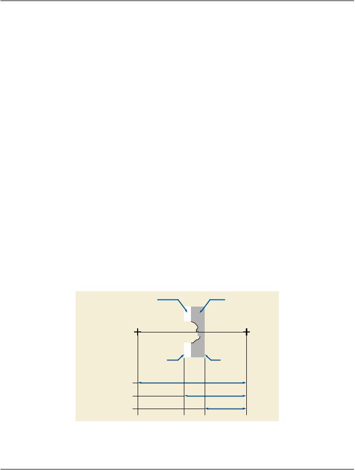
C.8.8.25.4 Virtual Source-Axis Distances and the Use of Trays in Ion Therapy
The apparent source position in ion therapy is not constant or can be different in x or y direction. The apparent source position (as measured from field size projections) shall be called Virtual Source, the distance from the virtual source to isocenter the Virtual SAD.
Most of the cases, no trays are used for blocks, compensators and wedges. However, the concept of trays together with the mounting position is useful for specifying exactly at which point the position of these devices shall be measured. Therefore, trays shall always be present, even though they are only virtual trays.
Figure C.8.8.25-1 shows an example.
Block |
|
|
|
Compensator |
( Mounting Position |
|
|
|
|
|
( Mounting Position |
|
|
|
|
= PATIENT SIDE ) |
|
|
|
|
|
= SOURCE SIDE ) |
Virtual |
|
|
|
|
|
|
|
|
|
|
|
|
Source (X/Y) |
|
|
|
|
|
Isocenter |
|
|
|
|
|
|
Block Tray |
|
|
|
|
|
Compensator Tray |
|
|
|
|
|
|
|
|
|
|
|
|
|
|
|
|
|
|
|
|
(virtual) |
|
|
|
(virtual) |
Virtual Source
Axis Distance
Isocenter to Block Tray
Distance
Isocenter to Compensator
Distance
Figure C.8.8.25-1. Virtual Source-Axis Distances
Examples: The use of the above Attributes for snout positioning and block/compensator manufacturing: