Материал: part03

Внимание! Если размещение файла нарушает Ваши авторские права, то обязательно сообщите нам

DICOM PS3.3 2020a - Information Object Definitions​

Page 761​

C.8.8.14.10 Compensator Transmission and Thickness Data Direction​

ThedirectionoftherowsandcolumnsinCompensatorTransmissionData(300A,00EB)andCompensatorThicknessData(300A,00EC)​ is defined as follows: The direction of rows goes along the positive Xb direction and the direction of the columns does along the​ negative Yb direction of the IEC X-BEAM LIMITING DEVICE coordinate system. Other interpretations shall be documented in an​ implementation's conformance statement.​

C.8.8.14.11 Block and Compensator Precedence for Dosimetric Calculations​

If Block Thickness (300A,0100) and Block Transmission (300A,0102) are present, Block Transmission shall have precedence for​ dosimetriccalculations.IfCompensatorTransmissionData(300A,00EB)andCompensatorThicknessData(300A,00EC)arepresent,​ Compensator Transmission Data shall have precedence for dosimetric calculations.​

C.8.8.14.12 Table Top Pitch and Table Top Roll​

Pitch and Roll Coordinate Systems of the Table Top are defined in IEC 61217 Edition 1.2 2008-04. These angles are defined as ro-​ tations of the IEC Table Top System as indicated below.​

The Table Top Pitch Angle is defined as the rotation of the coordinate axes Yt, Zt about axis Xt by an angle ψt; See Figure C.8.8.14-​ 1.AnincreaseinthevalueofangleψtcorrespondstotheclockwiserotationoftheTableTopasviewedfromtheTableTopcoordinate​ system origin along the positive Xt axis.​

The Table Top Roll Angle is defined as the rotation of the coordinate axes Xt, Zt about axis Yt by an angle ψt; See Figure C.8.8.14-​ 2.AnincreaseinthevalueofangleψtcorrespondstotheclockwiserotationoftheTableTopasviewedfromtheTableTopcoordinate​ system origin along the positive Yt axis.​

It is important to observe that the point of rotation is the origin of the table top system after the rotation of the PATIENT SUPPORT(s)​ system about Zs by θs after the rotation of the Table top eccentric rotation (e) system about Ze by θe and after the translation of Table​ top (t) system along Xe Ye Ze. This means that the rotation point of the Pitch and Roll angles is typically not the isocenter. The​ translational values Xt Yt Zt may need to be adjusted to preserve the patient position at the isocenter. e.g., a rotation of the Pitch​ angle by a positive angle at a position originally at Xt=0, Yt=100 and Zt=0 will lead to a negative Zt value and a slightly lower Yt if the​ patient position at isocenter is to be maintained.​

Ψt

Z t


Z’t

Y’t

Ψt

Y t

Xt - Yt Plane

X t

Figure C.8.8.14-1. Table Top Pitch Angle​

- Standard -​

Page 762​

DICOM PS3.3 2020a - Information Object Definitions​

φt

Z t

Z’t

Y’t

Xt - Yt Plane

X t

X’t φt

Figure C.8.8.14-2. Table Top Roll Angle​

C.8.8.14.13 Angular Values in RT Beams Module​

TheAttributesthatdefineanglesrefertocoordinatesystemsdefinedbyIEC61217.WhereindicatedintheDICOMAttributedefinition,​ the angle uses the coordinate system (orientation of the rotation axis and the origin of the rotating coordinate system) defined in IEC​ 61217, however DICOM makes no restrictions on the range of values stored. IEC 61217 defines restrictions that only apply to user​ interface presentation.​

C.8.8.14.14 Effective Wedge Angle​

The Effective Wedge Angle (300A,00DE) and Radiation Beam Effective Wedge Angle (300A,0654) describe the dosimetric angle of​ a motorized wedge accounting for the partial presence of the wedge in the beam. The presence of the wedge in the beam is either​ specified by the Wedge Position (300A,0118) in the Wedge Position Sequence (300A,0116) included in the Control Point Sequence​ (300A,0111) of the current beam or the RT Control Point Sequence of the current Radiation. When the wedge is in the beam​ throughout all control points, the Effective Wedge Angle (300A,00DE) and Radiation Beam Effective Wedge Angle (300A,0654) will​ havethesamevalueastheWedgeAngle(300A,00D5)orRadiationBeamWedgeAngle(300A,0652).OtherwisetheEffectiveWedge​ Angle(300A,00DE)orRadiationBeamEffectiveWedgeAngle(300A,0654)willhavealowervaluethantheWedgeAngle(300A,00D5)​ or Radiation Beam Wedge Angle (300A,0652).​

C.8.8.14.15 Source to External Contour Distance and External Contour Entry Point​

The Source to External Contour Distance (300A,0132) is the distance to the beam entry point (External Contour Entry Point), which​ may include Bolus, Patient Positioning Devices, Patient Immobilization Devices or other devices. This value is useful for including​ the attenuation effects of external devices on the dose calculation and for patient setup.​

C.8.8.14.16 Referenced Control Point​

The number of Items in the Beam Dose Verification Control Point Sequence (300A,008C) is not required to be the same as in the​ Control Point Sequence (300A,0111). A different sampling can be chosen for the Beam Dose Verification Control Point Sequence,​ but where the Cumulative Meterset Weight of a Control Point Sequence (300A,008C) Item is the same it shall be referenced by the​ Referenced Control Point Index (300C,00F0).​

C.8.8.15 RT Brachy Application Setups Module​

The RT Brachy Application Setups Module describes the application of a brachytherapy radiotherapy treatment. It contains one or​ moresources,eachassociatedwithoneormoreChannels.AChannelisadevicebywhichasourceisplacedinitsintendedtreatment​ position or positions. A Channel may consist of a Source Applicator plus a Transfer Tube, a Source Applicator alone, a rigid or flexible​ linear source, or a seed. A number of Channels (for example applicators, sources or seeds) are generally arranged in an Application​ Setup, which may be considered a "logical" device. It is important not to confuse Application Setup with Applicator. The model used​

- Standard -​

DICOM PS3.3 2020a - Information Object Definitions​

Page 763​

here has been primarily built around the concept of remote afterloading, but extended to support other brachytherapy applications​ such as manual applicators and molds, seeds, and sources. Additional devices that are not Channels are described as Brachy Ac-​ cessory Devices. Examples of Accessory Devices include shields that modify the dose distribution from all sources in the treatment.​ However, Channel shields modify the dose only for the source(s) in that Channel.​

The data in the Module are arranged as follows:​


Treatment Machine Sequence​

;treatment machine information (single Item)​

Source Sequence​

;library of sources used in brachy application​

Application Setup Sequence​

;one or more applicators, sources, seeds etc​

>Brachy Accessory Device Sequence​

;application level shields etc​

>Channel Sequence​

;applicator, line source(s), seed(s) etc​

>>Channel Shield Sequence​

;channel-specific shields​

>>Brachy Control Point Sequence​

;mechanism to support individual source dwell times​

Table C.8-51. RT Brachy Application Setups Module Attributes​

Attribute Name​

Tag​

Type​

Attribute Description​

Brachy Treatment Technique​

(300A,0200)​

1​ Type of brachytherapy treatment technique.​


Enumerated Values:​


INTRALUMENARY​


INTRACAVITARY​


INTERSTITIAL​


CONTACT​


INTRAVASCULAR​


PERMANENT​


See Section C.8.8.15.1.​

Brachy Treatment Type​

(300A,0202)​

1​ Type of brachytherapy treatment.​


Defined Terms:​


MANUAL​manually positioned​


HDR​

High dose rate​


MDR​

Medium dose rate​


LDR​

Low dose rate​


PDR​

Pulsed dose rate​

Treatment Machine Sequence​

(300A,0206)​

1​ ASequencedescribingtreatmentmachinetobeusedfortreatment​


delivery.​


Only a single Item shall be included in this Sequence.​

>Treatment Machine Name​

(300A,00B2)​

2​ User-defined name identifying treatment machine to be used for​


treatment delivery.​

>Manufacturer​

(0008,0070)​

3​ Manufacturer of the equipment to be used for treatment delivery.​

>Institution Name​

(0008,0080)​

3​ Institution where the equipment is located that is to be used for​


treatment delivery.​

>Institution Address​

(0008,0081)​

3​ Mailing address of the institution where the equipment is located​


that is to be used for treatment delivery.​

>InstitutionalDepartmentName​

(0008,1040)​

3​ Department in the institution where the equipment is located that​


is to be used for treatment delivery.​

- Standard -​

Page 764​

DICOM PS3.3 2020a - Information Object Definitions​

Attribute Name​

Tag​

Type​

Attribute Description​

>Institutional Department Type​

(0008,1041)​

3​

A coded description of the type of Department or Service within​

Code Sequence​


the healthcare facility.​


Only a single Item is permitted in this Sequence.​

>>Include Table 8.8-1 “Code Sequence Macro Attributes”​

BCID 7030 “Institutional Departments, Units and Services”.​

>Manufacturer's Model Name​

(0008,1090)​

3​

Manufacturer's model name of the equipment that is to be used​


for treatment delivery.​

>Device Serial Number​

(0018,1000)​

3​

Manufacturer's serial number of the equipment that is to be used​


for treatment delivery.​

Source Sequence​

(300A,0210)​

1​

Sequence of Sources to be used within Application Setups. One​


or more Items shall be included in this Sequence.​

>Source Number​

(300A,0212)​

1​

Identification number of the Source. The value of Source Number​


(300A,0212) shall be unique within the RT Plan in which it is​


created.​

>Source Serial Number​

(3008,0105)​

3​

Identifier for the Source Instance. Identifies the actual source​


instance of the source, to which Source Strength Reference Date​


(300A,022C) and Source Strength Reference Time (300A,022E)​


refer.​

>Source Model ID​

(300A,021B)​

3​

Identifier for the Source Model. Identifies the model, the source​


instance belongs to.​

>Source Description​

(300A,021C)​

3​

Description of the source.​

>Source Type​

(300A,0214)​

1​

Type of Source.​


Defined Terms:​


POINT​


LINE​


CYLINDER​


SPHERE​

>Source Manufacturer​

(300A,0216)​

3​

Manufacturer of Source.​

>Active Source Diameter​

(300A,0218)​

3​

Diameter of active Source (mm).​

>Active Source Length​

(300A,021A)​

3​

Length of active Source (mm).​

>Material ID​

(300A,00E1)​

3​

User-suppliedidentifierforencapsulationmaterialofactiveSource.​

>SourceEncapsulationNominal​

(300A,0222)​

3​

Nominal thickness of wall of encapsulation (mm). See​

Thickness​


Section C.8.8.15.12.​

>SourceEncapsulationNominal​

(300A,0224)​

3​

Nominal transmission through wall of encapsulation (between 0​

Transmission​


and 1). See Section C.8.8.15.12​

>Source Isotope Name​

(300A,0226)​

1​

Name of Isotope.​

>Source Isotope Half Life​

(300A,0228)​

1​

Half-life of Isotope (days).​

>Source Strength Units​

(300A,0229)​

1C​

Measurement unit of Source Strength.​


Required if the source is not a gamma-emitting (photon) source.​


May be present otherwise.​

Enumerated Values:​

AIR_KERMA_RATE​AirKermaRateifSourceisGammaemitting​ Isotope.​

DOSE_RATE_WATER​Dose Rate in Water if Source is Beta​ emitting Isotope.​

- Standard -​


DICOM PS3.3 2020a - Information Object Definitions​

Page 765​

Attribute Name​

Tag​

Type​

Attribute Description​


>Reference Air Kerma Rate​

(300A,022A)​

1​

Air Kerma Rate in air of Isotope specified at Source Strength​


ReferenceDate(300A,022C)andSourceStrengthReferenceTime​


(300A,022E)(inµGyh-1 at1m).Valueshallbezerofornon-gamma​


sources.​


>Source Strength​

(300A,022B)​

1C​

Source Strength of Isotope at Source Strength Reference Date​


(300A,022C) and Source Strength Reference Time (300A,022E),​


in units specified in Source Strength Units (300A,0229).​


Required if the source is not a gamma-emitting (photon) source.​


See Section C.8.8.15.13.​


>Source Strength Reference​

(300A,022C)​

1​

Reference date for Reference Air Kerma Rate (300A,022A) or​

Date​


Source Strength (300A,022B) of Isotope.​


>Source Strength Reference​

(300A,022E)​

1​

ReferencetimeforAirKermaRate(300A,022A)orSourceStrength​

Time​


(300A,022B) of Isotope.​


Application Setup Sequence​

(300A,0230)​

1​

Sequence of Application Setups for current RT Plan.​


One or more Items shall be included in this Sequence.​

>Application Setup Type​

(300A,0232)​

1​

Type of Application Setup.​


Defined Terms:​


FLETCHER_SUIT​


DELCLOS​


BLOEDORN​


JOSLIN_FLYNN​


CHANDIGARH​


MANCHESTER​


HENSCHKE​


NASOPHARYNGEAL​


OESOPHAGEAL​


ENDOBRONCHIAL​


SYED_NEBLETT​


ENDORECTAL​


PERINEAL​


>Application Setup Number​

(300A,0234)​

1​

Identification number of the Application Setup. The value of​


Application Setup Number (300A,0234) shall be unique within the​


RT Plan in which it is created.​


>Application Setup Name​

(300A,0236)​

3​

User-defined name for Application Setup.​


>Application Setup​

(300A,0238)​

3​

Manufacturer of Application Setup.​


Manufacturer​


>Template Number​

(300A,0240)​

3​

Identification number of the Template. The value of Template​


Number (300A,0240) shall be unique within the Application Setup​


in which it is created.​


>Template Type​

(300A,0242)​

3​

User-defined type for Template Device.​


>Template Name​

(300A,0244)​

3​

User-defined name for Template Device.​


>Referenced Reference Image​

(300C,0042)​

3​

Sequence of reference images used for validation of current​

Sequence​


Application Setup.​


One or more Items are permitted in this Sequence.​


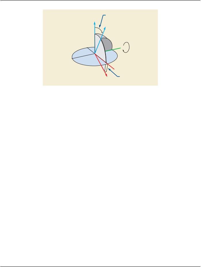
>>IncludeTable10-11“SOPInstanceReferenceMacroAttributes”​

- Standard -​