Материал: part03

Внимание! Если размещение файла нарушает Ваши авторские права, то обязательно сообщите нам

DICOM PS3.3 2020a - Information Object Definitions​

Page 771​

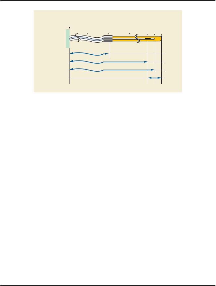
Control Point 0: Control Point Relative Position = 30, Cumulative Time Weight = 0​

Control Point 1: Control Point Relative Position = 30, Cumulative Time Weight = 25​

Control Point 2: Control Point Relative Position = 20, Cumulative Time Weight = 27​

Control Point 3: Control Point Relative Position = 20, Cumulative Time Weight = 52​

Control Point 4: Control Point Relative Position = 10, Cumulative Time Weight = 54​

Control Point 5: Control Point Relative Position = 10, Cumulative Time Weight = 79​

f) Stepwise motion with consideration of source transit times between dwell positions and to first and from last dwell position; Three​ equally weighted dwell positions; Step size = 10; Final Cumulative Time Weight = 383:​

Control Point 0: Control Point Relative Position = 1200, Cumulative Time Weight = 0​

Control Point 1: Control Point Relative Position = 30, Cumulative Time Weight = 150​

Control Point 2: Control Point Relative Position = 30, Cumulative Time Weight = 175​

Control Point 3: Control Point Relative Position = 20, Cumulative Time Weight = 177​

Control Point 4: Control Point Relative Position = 20, Cumulative Time Weight = 202​

Control Point 5: Control Point Relative Position = 10, Cumulative Time Weight = 204​

Control Point 6: Control Point Relative Position = 10, Cumulative Time Weight = 229​

Control Point 7: Control Point Relative Position = 1200, Cumulative Time Weight = 383​

C.8.8.15.8 Source Transit Time​

The Source transit times between dwell positions of a remote afterloader may be considered by specifying a non-zero increment in​ the Cumulative Time Weight (300A,02D6) when the Source moves between Control Points. In this case the Channel Total Time​ (300A,0286) shall include the overall Source transit time for the Channel.​

C.8.8.15.9 Control Point Relative Position​

Control Point Relative Position (300A,02D2) shall describe where the center of a given source in a channel is located with respect to​ the end of the channel, i.e. to the center of the distal-most possible dwell position in the channel.​

C.8.8.15.10 Control Point 3D Position​

Control Point 3D Position (300A,02D4) shall describe the absolute 3D coordinates of a source. This position shall correspond to the​ center of a source in an applicator during a remote or manually controlled afterloading treatment.​

C.8.8.15.11 Cumulative Dose Reference Coefficient​

The Cumulative Dose Reference Coefficient (300A,010C) is the value by which Brachy Application Setup Dose (300A,00A4) is mul-​ tiplied to obtain the dose to the referenced dose reference site at the current control point (and after previous control points have been​ successfully administered). The Cumulative Dose Reference Coefficient (300A,010C) is by definition zero for the initial control point.​ The Cumulative Dose Reference Coefficient (300A,010C) of the final control point multiplied by Brachy Application Setup Dose​ (300A,00A4)resultsinthefinaldosetothereferenceddosereferencesiteforthecurrentchannel.Dosecalculationfordosereference​ sites other than points is not well defined.​

IfTreatmentType(300A,0202)isPDR,thentheCumulativeDoseReferenceCoefficient(3008,010C)shallspecifythedosedelivered​ to the dose reference during a single pulse. The total dose delivered to the dose reference shall then be expressed by Cumulative​ Dose Reference Coefficient (3008,010C) multiplied by Number of Pulses (300A,028A) multiplied by Brachy Application Setup Dose​ (300A,00A4).​

- Standard -​

Page 772​

DICOM PS3.3 2020a - Information Object Definitions​

C.8.8.15.12 Nominal Thickness and Nominal Transmission​

If provided, Source Encapsulation Nominal Thickness (300A,0222), Brachy Accessory Device Nominal Thickness (300A,026A),​ Source Applicator Wall Nominal Thickness (300A,029C), and Channel Shield Nominal Thickness (300A,02B8) shall indicate that the​ related objects are of uniform thickness with the specified value. If this is not the case, these Attributes shall not be provided.​

Ifprovided,SourceEncapsulationNominalTransmission(300A,0224),BrachyAccessoryDeviceNominalTransmission(300A,026C),​ Source Applicator Wall Nominal Transmission (300A,029E), and Channel Shield Nominal Transmission (300A,02BA) shall indicate​ thattherelatedobjectsareofuniformtransmissionwiththespecifiedvalue.Ifthisisnotthecase,theseAttributesshallnotbeprovided.​

No assumptions are made about the source characteristics beyond the parameters specified here.​

C.8.8.15.13 Reference Point for Calibration of Beta Emitting Isotopes​

For beta emitting isotopes, Source Strength (300A,022B) shall be defined at reference point (r0,θ0), where r0 is the radial distance​ of 2 mm from the source longitudinal axis, and θ0 is the angle of 90 degrees between the source longitudinal axis and the line defined​ by the center of the source and the reference point. Refer to:​

•​IEC 60601-2-17 (Medical electrical equipment - Particular requirements for the safety of automatically-controlled brachytherapy​ afterloading equipment), where the beta source strength is defined as: ABSORBED DOSE RATE [Gy s-1] in water at 2 mm along​ the perpendicular bisector from a RADIOACTIVE SOURCE emitting beta RADIATION.​

•​Nath et. al.: Intravascular brachytherapy physics: Report of the AAPM Radiation Therapy Committee Task Group No. 60, Med.​ Phys 26 (2) Feb 1999, pp 119-152.​

C.8.8.15.14 Orientation of Brachy Sources​

The Control Point Orientation (300A,0412) shall be used to define the orientation of an anisotropic brachytherapy source or seed for​ the purpose of calculating the effect of the anisotropy on the dose calculation. The Control Point Orientation (300A,0412) shall be​ given by the direction vector of the long axis of the Brachy source or seed in the insertion direction, in the DICOM Patient-Based​ Coordinate System. The direction vector shall be oriented from the source center as defined by the Control Point 3D Position​ (300A,02D4) along the long axis of the source and in the insertion direction.​

C.8.8.15.15 Source Model ID​

The Source Model ID (300A,021B) ties together the physical source properties. The creator of the plan has used this ID to select the​ radioactive source model for the plan. An example would be the name of the used TG-43 data.​

C.8.8.15.16 Geometric Parameters​

A Channel is the combination of the Transfer Tube and the Source Applicator. A Channel is physically connected to one of the con-​ nection sockets of the afterloader. Afterloader Channel ID (300A,0273) unambiguously identifies the afterloader channel to which the​ applicator is connected; see Section C.8.8.15.16.2. Both Afterloader Channel ID (300A,0273) and Source Applicator ID (300A,0291)​ describe the connection between the afterloader and the applicator (so called channel mapping). Channel Number (300A,0282) is​ used to index the Items within the Channel Sequence (300A,0280) and does not serve as the identification of the channel socket at​ the afterloader.​

- Standard -​

DICOM PS3.3 2020a - Information Object Definitions​

Page 773​

Afterloader

Transfer Tube *

Source-Applicator Source Applicator

Center of distal-most source position


connector


Source Applicator lumen end


Source Applicator tip


Transfer Tube Length

(300A,02A4)

Channel Effective Length

(300A,0271)

Channel Inner Length

(300A,0272)

Source Applicator Tip Length

(300A.0274)

* The Transfer Tube may not be used. In that case, the Source Applicator is directly connected to the Afterloader.

Figure C.8.8.15-1. RT Brachy Channel Geometric Parameters​

Note​

Channel Length (300A,0284) has been interpreted in different ways. Channel Effective Length (300A,0271) should be used​ instead, as the distance from the afterloader to the center of the distal-most possible dwell position following the definition​ in Figure C.8.8.15-1.​

Additionally, the Transfer Tube Length (300A,02A4) may be specified. If Transfer Tube Length (300A,02A4) is absent or​ has no value, the distance from the Source Applicator connector to the center of the distal-most possible dwell position is​ equaltothevalueoftheChannelEffectiveLength(300A,0271).IfTransferTubeLength(300A,02A4)hasavalue,thedistance​ from the Source Applicator connector to the center of the distal-most possible dwell position is equal to the Channel Effective​ Length (300A,0271) minus the Transfer Tube Length (300A,02A4). The concept of Source Applicator Length (300A,0296)​ should not be used any longer.​

C.8.8.15.16.1 Channel Inner Length​

The Channel Inner Length (300A,0272) is the measurable physical inner length of the channel. It specifies the distance between the​ connector on the afterloader and the inner end of the channel. In the RT Brachy Session Record Module it shall be specified as the​ measured or verified length.​

C.8.8.15.16.2 Afterloader Channel ID​

The Afterloader Channel ID (300A,0273) is the connector socket identification on the afterloader where the channel is connected.​

- Standard -​

Page 774​

DICOM PS3.3 2020a - Information Object Definitions​

Applicator Setup Sequence (300A,0230)

Item 1

>Channel Sequence (300A,0280)

Item 1

>>Channel Number (300A,0282)

>>Afterloader Channel ID (300A,0273)

>>...

>>Source Applicator Number (300A,0290)

>>Source Applicator ID (300A,0291)

>Applicator Setup Name (300A,0236)

Item 1

12

1

2


11


3

10 Afterloader

4

9


5

8

7

6


A1 A2 A3 A4

A5

A6

A7

A8


Source Applicator


Figure C.8.8.15-2. RT Brachy Channel and Applicator IDs​

C.8.8.16 Approval Module​

Table C.8-52. Approval Module Attributes​

Attribute Name​

Tag​

Type​

Attribute Description​

Approval Status​

(300E,0002)​

1​

Approval status at the time the SOP Instance was created.​


Enumerated Values:​


APPROVED​ Reviewer recorded that object met an implied criterion​


UNAPPROVED​No review of object has been recorded​


REJECTED​ Reviewerrecordedthatobjectfailedtomeetanimplied​


criterion​

Review Date​

(300E,0004)​

2C​

Date on which object was reviewed. Required if Approval Status​


(300E,0002) is APPROVED or REJECTED.​

Review Time​

(300E,0005)​

2C​

Time at which object was reviewed. Required if Approval Status​


(300E,0002) is APPROVED or REJECTED.​

Reviewer Name​

(300E,0008)​

2C​

Name of person who reviewed object. Required if Approval Status​


(300E,0002) is APPROVED or REJECTED.​

C.8.8.17 RT General Treatment Record Module​

Table C.8-53. RT General Treatment Record Module Attributes​

Attribute Name​

Tag​

Type​

Attribute Description​

Instance Number​

(0020,0013)​

1​

Instancenumberidentifyingthisparticularinstanceofthe​


object.​

Treatment Date​

(3008,0250)​

2​

Date when current fraction was delivered, or Date last​


fractionwasdeliveredincaseofRTTreatmentSummary​


Record IOD. See Note.​

Treatment Time​

(3008,0251)​

2​

Time when current fraction was delivered (begun), or​


Time last fraction was delivered (begun) in case of RT​


Treatment Summary Record IOD. See Note.​

ReferencedRTPlanSequence​

(300C,0002)​

2​

Reference to a RT Plan.​


Zero or one Item shall be included in this Sequence.​

- Standard -​


DICOM PS3.3 2020a - Information Object Definitions​

Page 775​

Attribute Name​

Tag​

Type​

Attribute Description​


>Include Table 10-11 “SOP Instance Reference Macro Attributes”​


Referenced Treatment Record​

(3008,0030)​

3​

ReferencetoRTTreatmentRecordstowhichthecurrent​

Sequence​


RT Treatment Record is significantly related.​

One or more Items are permitted in this Sequence.​

>Include Table 10-11 “SOP Instance Reference Macro Attributes”​

Note​

TreatmentDate(3008,0250)andTreatmentTime(3008,0251)canbeusedtochronologicallyorderasequenceoftreatments,​ where each treatment is represented by an instance of a RT Beams Treatment Record or RT Brachy Treatment Record. In​ the case of a RT Treatment Summary Record, it can be used to identify the period for which the treatment summary is valid.​ Therefore, implementers are strongly advised to include values for these Attributes whenever possible.​

C.8.8.18 RT Treatment Machine Record Module​

Table C.8-54. RT Treatment Machine Record Module Attributes​

Attribute Name​

Tag​

Type​

Attribute Description​

Treatment Machine Sequence​

(300A,0206)​

1​

Sequencedescribingtreatmentmachineusedfortreatment​


delivery.​


Only a single Item shall be included in this Sequence.​

>Treatment Machine Name​

(300A,00B2)​

2​

User-defined name identifying treatment machine used for​


treatment delivery.​

>Manufacturer​

(0008,0070)​

2​

Manufacturer of the equipment used for treatment delivery.​

>Institution Name​

(0008,0080)​

2​

Institution where the equipment is located that was used for​


treatment delivery.​

>Institution Address​

(0008,0081)​

3​

Mailing address of the institution where the equipment is​


located that was used for treatment delivery.​

>Institutional Department Name​

(0008,1040)​

3​

Departmentintheinstitutionwheretheequipmentislocated​


that was used for treatment delivery.​

>Institutional Department Type​

(0008,1041)​

3​

A coded description of the type of Department or Service​

Code Sequence​


within the healthcare facility.​


Only a single Item is permitted in this Sequence.​

>>Include Table 8.8-1 “Code Sequence Macro Attributes”​


BCID 7030 “Institutional Departments, Units and Services”.​

>Manufacturer's Model Name​

(0008,1090)​

2​

Manufacturer's model name of the equipment used for​


treatment delivery.​

>Device Serial Number​

(0018,1000)​

2​

Manufacturer's serial number of the equipment used for​


treatment delivery.​

C.8.8.19 Measured Dose Reference Record Module​

Table C.8-55. Measured Dose Reference Record Module Attributes​

Attribute Name​

Tag​

Type​

Attribute Description​

Measured Dose Reference​

(3008,0010)​

1​

Sequence of doses measured during treatment delivery, summed​

Sequence​


over entire session.​

One or more Items shall be included in this Sequence.​

- Standard -​