Материал: m912201e
The Editors • 219
The Graphic Editors
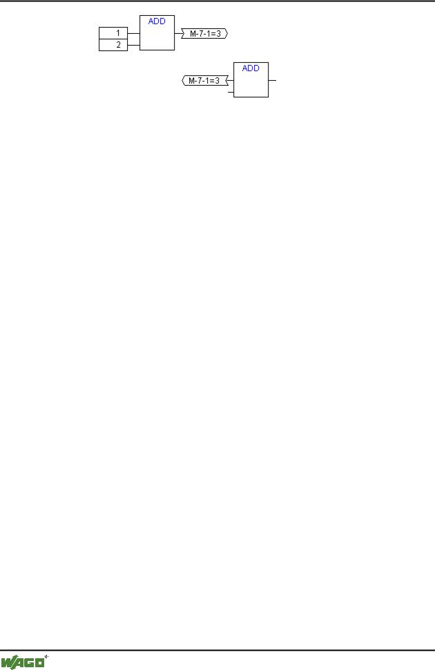
The data type of a constant is obtained from the smallest possible data type, that is the constant '1' adopts the data type SINT. If now an addition with feedback and the constant '1' is executed, the first input gives the data type SINT and the second is undefined because of the feedback. Thus the intermediate variable is also of the type SINT. The value of the intermediate variable is only then allocated to the output variable.
The diagram below shows an addition with feedback and an addition with a variable. The variables x and y should be of the type INT here.
There are differences between the two additions:
The variable y can be initialised with a value which is not equal to zero but this is not the case for intermediate variable for the left addition.
The intermediate variable for the left addition has the data type SINT while that on the right has the data type INT. The variables x and y have different values after the 129th call up. The variable x, although it is of the type INT, contains the value - 127 because the intermediate variable has gone into overflow. The variable y contains the value 129, on the other hand.
5.4.5.36CFC in Online mode
Monitoring:
The values for inputs and outputs are displayed within the input or output boxes. Constants are not monitored. For non-boolean variables, the boxes are expanded to accommodated the values displayed. For boolean connections, the variable name as well as the connection are displayed in blue if the value is TRUE, otherwise they remain black.
Internal boolean connections are also displayed Online in blue in the TRUE state, otherwise black. The value of internal non-boolean connections is displayed in a small box with rounded corners on the output pin of the connection.
PINs in macros are monitored like inor output boxes.
WAGO-I/O-SYSTEM 759 WAGO-I/O-PRO 32
220 • The Editors
The Graphic Editors
Non-boolean connections with connection markers display their value within the connection marker. For boolean connections, the lines as well as the marker names are displayed in blue if the line is carrying the value TRUE, otherwise black.
Flow control:
When flow control is switched on, the connections that have been traversed are marked with the color selected in the project options.
Breakpoints:
Breakpoint s can be set on all elements that also have a processing sequence order index. The processing of the program will be halted prior to execution of the respective element, that is for POUs and outputs before the assignment of inputs, for jump labels before execution of the element with the next index. The processing sequence index of the element is used as the breakpoint position in the Breakpoint dialog.
The setting of breakpoints on a selected element is accomplished with the F9 key or via the menu item 'Breakpoint on/off' in the 'Online' or 'Extras' menu or in the editor's context menu. If a breakpoint is set on an element, then this will be erased and reversed the next time the command 'Breakpoint on/off' is executed. In addition, the breakpoint on an element can be toggled by doubleclicking on it.
Breakpoints are displayed in the colors entered in the project options.
RETURN label:
In Online mode, a jump label with the name "RETURN" is automatically generated in the first column and after the last element in the editor. This label marks the end of the POU and is jumped to when stepping just before execution leaves the POU. No RETURN marks are inserted in macros.
Stepping:
When using 'Step over' the element with the next-higher order index will always be jumped to. If the current element is a macro or a POU, then its implement branches when 'Step in' is in effect. If a 'Step over' is executed from there, the element whose order index follows that of the macro is jumped to.
WAGO-I/O-SYSTEM 759 WAGO-I/O-PRO 32
Overview of the Resources |
• 221 |
Global Variables |
|
|
|
6 Overview of the Resources
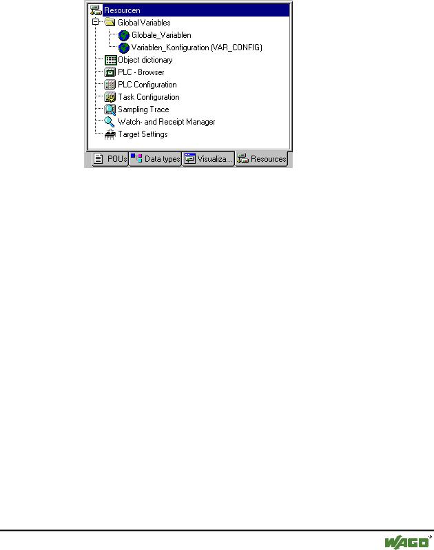
In the Resources register card of the Object Organizer, there are objects for configuring and organizing your project and for keeping track of the values of the variables:
x Resources
6.1 Global Variables
6.1.1 Editing Global Variables
In the Object Organizer, you will find three objects in the Resources register card in the Global Variables folder (default names of the objects in parentheses).
All variables defined in these objects are recognized throughout the project.
If the global variables folder is not opened up (plus sign in front of the folder), you can open it with a doubleclick <Enter> in the line.
Select the corresponding object. The 'Object Open' command opens a window with the previously defined global variables. The editor for this works the same way as the declaration editor.
6.1.2 Several Variables Lists
Global variables, and variable configurations (VAR_CONFIG) must be defined in separate objects.
If you have declared a large number of global variables, and you would like to structure your global variables list better, then you can create further variables lists.
In the Object Organizer, select the Global Variables folder or one of the existing  objects with global variables. Then execute the 'Project' 'Object
WAGO-I/O-SYSTEM 759 WAGO-I/O-PRO 32
222 • Overview of the Resources
Global Variables
Add' command. Give the object that appears in the dialog box a corresponding name. With this name an additional object will be created with the key word VAR_GLOBAL. If you prefer an object a variable configuration, change the corresponding key word to VAR_CONFIG.
6.1.3 Global Variables
"Normal" variables, constants or remanent variables that are known throughout the project can be declared as global variables.
6.1.3.1 Create a Global Variable List
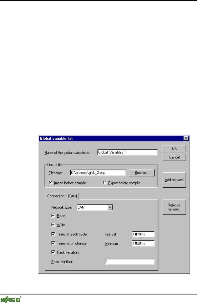
To create a Global Variable List, open the register 'Resources' in the Object Organizer and select the entry 'Global Variables' or select an already existing list. Then choose the command 'Project' 'Object' 'Add' to open the dialog Global variable list.
This dialog can also be opened by the command 'Project' 'Object' 'Properties' which is available if an existing Global Variable List is marked in the object organizer. It shows the configuration of this list..
x Dialog to create a new Global Variable List
If the option 'Support network variables' is activated in the target settings, then the button <Add network> is available. Pressing this button the dialog gets
WAGO-I/O-SYSTEM 759 WAGO-I/O-PRO 32

Overview of the Resources |
• 223 |
Global Variables |
|
|
|
extended and looks like shown in the picture. If the option is not activated, the button is not available.
Insert a Name of the global variable list. If you have an export file (*.exp) or a DCF file, which contains the desired variables, you can set up a link to this file (Link to file). To do this, insert the path of the file in the field Filename resp. press the button Browse to get the standard dialog 'Select text file'. DCF files are converted to ICE syntax when they are read in.
Activate option Import before compile, if you wish that the variable list will be read from the external file before each compilation of the project. Activate the option Export before compile, if you want the variable list to be written to the external file before each compilation of the project.
If no configuration is yet present, you will get in the case of a CAN network a single tabulator sheet with the inscription 'Connection 1 (CAN)'. Each time the 'Add network' button is pressed again, you get up to four more sheets inscribed with serial numbers after "Connection".
Choose the desired type from the list following Network type. The list is defined by the target system entries. For example, "CAN" as an abbreviation for a CAN network, or "UDP" for a UDP transmission system, might be selectable.
The following options can be activated or deactivated in configuring the transmission behavior of the variables:
Read: The variables in the list are read; if the option is deactivated, further variables sent over the net will be ignored.
Write: The variables are written; the following options apply:
Transmit each cycle: Variables are written within the intervals specified after Interval. (time notation e.g. T#70ms).
Transmit on change: Variables are written only when their values change; an entry after Minimum can, however, set a minimum time lapse between transfers.
Pack variables: The variables are assembled for transfer into packets whose size depends on the network. If the option is deactivated, a packet is set up for each variable.
Base identifier: The packets in which the variables are sent are given an identification number which in the standard case begins with 1 and is assigned in rising order, so long as you do not enter another starting number here.
6.1.3.2 Editing Global Variable Lists
The editor for global variables works similar to the declaration editor. But note that you cannot edit in this editor an list, which is an image of an linked
WAGO-I/O-SYSTEM 759 WAGO-I/O-PRO 32