Материал: m912201e
The Editors • 209
The Graphic Editors
x should initialised to 1 and y initialised to 0. The numbers in the right corner of the block indicate the order in which the commands are executed.
x will be increased by one until it reaches the value 10. This causes the output of the block LT(0) to deliver the value FALSE and SUB(3) and ADD(5) will be executed. x is set back to the value 1 and y is increased by 1. LT(0) is executed again as long as x is smaller than 10. y thus count the number of times x passes though the value range 1 to 10.
5.4.5.14‚Extras' ‚Properties...' in CFC
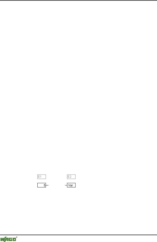
Constant input parameters (VAR_INPUT CONSTANT) from functions and function blocks are not shown directly in the continuous function chart editor. These can be shown and their value can be changed when one selects the trunk of the block in question and then selects the command ‚Extras' ‚Properties' or simply double clicks on the trunk. The "Edit parameters" dialog opens:
x Properties dialog
The values of the constant input parameter (VAR_INPUT CONSTANT) can be changed. Here it is necessary to mark the parameter value in the column
WAGO-I/O-SYSTEM 759 WAGO-I/O-PRO 32
210 • The Editors
The Graphic Editors
Value. Another mouse click or pressing on the space bar allows this to be edited. Confirmation of the change to the value is made by pressing the <Enter> key or pressing <Escape> rejects the changes. The button OK stores all of the changes which were made.
5.4.5.15Selecting elementsin CFC
One clicks on the trunk of the element to select it.
To mark more elements one presses the <Shift> key and clicks in the elements required, one after the other, or one drags the mouse with the left hand mousekey depressed over the elements to be marked.
The command 'Extras' 'Select all' marks all elements at once.
5.4.5.16Moving elementsin CFC
One or more selected elements can be moved with the arrow keys as one is pressing on the <Shift> key. Another possibility is to move elements using a depressed left mousekey. These elements are placed by releasing the left mousekey in as far as they do not cover other elements or exceed the foreseen size of the editor. The marked element jumps back to its initial position in such cases and a warning tone sounds.
5.4.5.17Copying elementsin CFC
One or more selected elements can be copied with the command 'Edit' 'Copy' and inserted with the command 'Edit' 'Paste'.
5.4.5.18Creating connections
An input of an element can be precisely connected to the output of another element. An output of an element can be connected to the inputs of a number of other elements.
There are a number of possibilities to connect the input of an element E2 with the output of an element E1.
Place the mouse on the output of element E1, click with the left mousekey, hold the left mousekey down and drag the mouse cursor onto the input of element E2 and let the left mousekey go. A connection is made from the output of element E1 to the mouse cursor during this dragging operation with the mouse.
Place the mouse on the input of element E2, click with the left mousekey, hold the left mousekey down and drag the mouse cursor onto the output of element E1 and let the left mousekey go.
WAGO-I/O-SYSTEM 759 WAGO-I/O-PRO 32
The Editors • 211
The Graphic Editors
Move one of the elements E1 or E2 and place it in such a way by letting go of the left mousekey that the output of element E2 and the input of element E1 touch.
Where element E2 is a block with a free input, a connection can also be made by dragging the mouse from an output from E1 to the trunk of E2. A connection with the free input at the highest position on E2 will be created when the mousekey is released. In the case where block E2 does not have a free input but is an operator which can have an input added to it, a new input will be automatically generated.
The output and input of a block can be connected together (feedback path) by using this method. To establish a connection between two pins, click with the left mouse button on one pin, hold the button down and thus drag the connection to the desired pin, where you then release the button. If during the dragging of the connection extends outside working area of the editor, scrolling occurs automatically. For simple data types, type testing is carried out during the connection. If the types of the two pins are not compatible, the cursor changes to "Forbidden". For complex data types, no testing takes place.
5.4.5.19Deleting connections
There are a number of possibilities for removing the connection between the output of an element E1 and the input of an element E2:
Select the output of element E1 and press the <Delete> key or execute the command 'Edit' 'Delete'. Several connections will be removed at the same if the output of E1 is connected to more than one of inputs.
Select the input of element E2 and press the <Delete> key or execute the command 'Edit' 'Delete'.
Select the input of E2 with the mouse, hold the left mousekey depressed and drag the connection from the input to E2 away. The connection is removed when the left mousekey is released in a free area of the screen.
5.4.5.20Changing connections
A connection between the output of an element E1 and the input of an element E2 can easily be changed into a connection between the output of element E1 and the input of element E3. The mouse is clicked on the input of E2, the left mousekey is kept depressed, the mouse cursor is moved to the input of E3 and then released.
5.4.5.21'Extras' 'Connection marker'
Connections can also be represented by a connector (connection marker) instead of a connecting line. Here the output and the associated input have a connector added to them which is given a unique name.
WAGO-I/O-SYSTEM 759 WAGO-I/O-PRO 32
212 • The Editors
The Graphic Editors
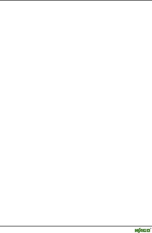
Where a connection already exists between the two elements which should now be represented by connectors, the output of the connecting line is marked and the menu point ‚Extras' ‚Connection marker' is selected. The following diagram shows a connection before and after the selection of this menu point.
A unique name is given as standard by the program which begins with M, but which can be changed The connector name is stored as an output parameter, but can be edited both at the input and at the output.
It is important to know that the connector name is associated with a property of the output of a connection and is stored with it.
1. Edit the connector at the output: 
If the text in the connector is replaced, the new connector name is adopted by all associated connectors at the inputs. One cannot, however, select a name which already belongs to another connection marker since the uniqueness of the connector name would be violated.
2. Edit the connector at the input: 
If the text in a connector is replaced, it will also be replaced in the corresponding connection marker on the other POU. Connections in connector representations can be converted to normal connections in that one marks the output of the connections (Cursor position 4) and again selects the menu point
'Extras' 'Connection marker'.
5.4.5.22Insert inputs/outputs "on the fly"
If exactly one input or output pin of an element is selected, then the corresponding inputor outputelement can be directly inserted and its editor field filled with a string by entering the string at the keyboard.
5.4.5.23Order of execution
The elements block, output, jump, return and label each possess a number indicating the order in which they are executed. In this sequential order the individual elements are evaluated at run time.
When pasting in an element the number is automatically given according to the topological sequence (from left to right and from above to below). The new element receives the number of its topological successor if the sequence has already been changed and all higher numbers are increased by one.
The number of an element remains constant when it is moved.
WAGO-I/O-SYSTEM 759 WAGO-I/O-PRO 32
The Editors • 213
The Graphic Editors
The sequence influences the result and must be changed in certain cases.
If the sequence is displayed, the corresponding sequential execution number is shown in the upper right hand corner of the element.
5.4.5.24'Extras' 'Order' 'Display'
This command switches the display of the order of execution on and off. The default setting is to show it (recognised by a tick ( ) in front of the menu point).
The relevant order of execution number appears in the upper right hand corner for the elements block, output, jump, return and label.
5.4.5.25'Extras' 'Order' 'Order topologically'
Elements are ordered in a topological sequence when the execution takes place from left to right and from above to below, that is the number increases from left to right and from above to below for topologically arranged elements. The connections are not relevant, only the location of the elements is important.
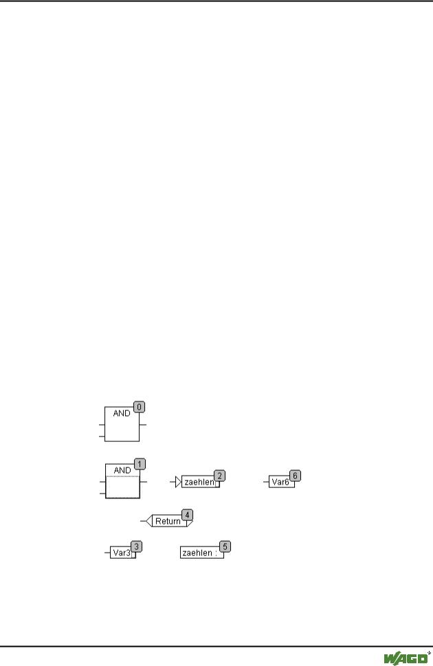
All selected elements are topologically arranged when the command 'Extras' 'Order' 'Order topologically' is executed. All elements in the selection are taken out of the sequential processing list by this process. The elements are then entered into the remaining sequential processing list individually from bottom right through to upper left. Each marked element is entered into the sequential processing list before its topological successor, i.e. it is inserted before the element that in a topological sequencing would be executed after it, when all elements in the editor were sequenced according to a topological sequencing system. This will be clarified by an example.
The elements with numbers 1, 2 and 3 are selected. If the command 'Order topologically' is selected the elements are first taken out of the sequential processing list. Var3, the jump and the AND-operator are then inserted again one after the other. Var3 is placed before the label and receives the number 2. The jump is then ordered and receives the number 4 at first but this then
WAGO-I/O-SYSTEM 759 WAGO-I/O-PRO 32