Материал: m912201e
214 • The Editors
The Graphic Editors
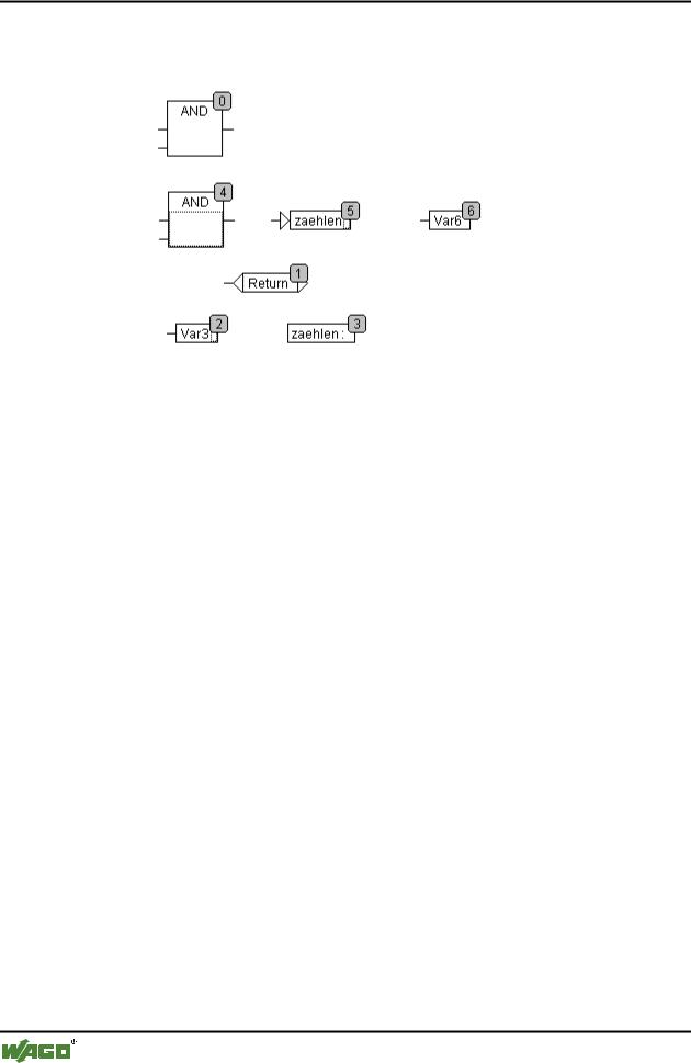
becomes 5 after the AND is inserted. The new order of execution which arises is:
When a newly generated block is introduced it will be placed by default in front of its topological successor in the sequential processing list.
5.4.5.26'Extras' 'Order' 'One forwards'
With this command all selected elements with the exception of the element which is at the beginning of the sequential processing list are moved one place forwards in the sequential processing list.
5.4.5.27'Extras' 'Order' 'One backwards'
With this command all selected elements with the exception of the element which is at the end of the sequential processing list are moved one place backwards in the sequential processing list.
5.4.5.28'Extras' 'Order' 'To the beginning'
With this command all selected elements will be moved to the front of the sequential processing list whereby the order within the group of selected elements is maintained. The order within the group of unselected elements also remains the same.
5.4.5.29'Extras' 'Order' 'To the end'
With this command all selected elements will be moved to the end of the sequential processing list whereby the order within the group of selected elements is maintained. The order within the group of unselected elements also remains the same.
5.4.5.30'Extras' 'Order' 'Order everything according to data flow''
This command effects all elements. The order of execution is determined by the data flow of the elements and not by their position.
WAGO-I/O-SYSTEM 759 WAGO-I/O-PRO 32
The Editors • 215
The Graphic Editors
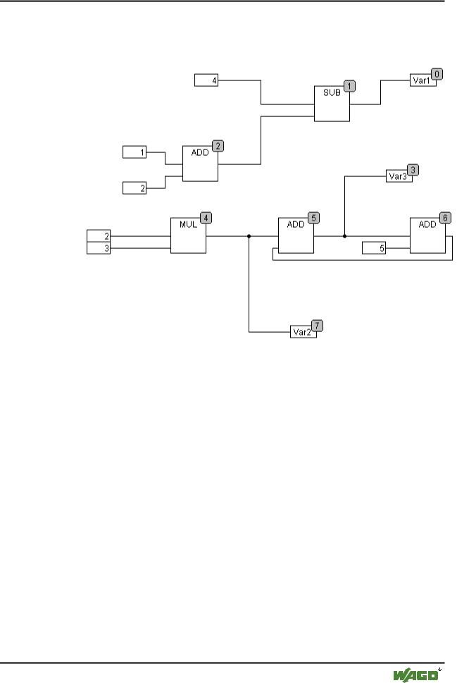
The diagram below shows elements which have been ordered topographically. x Sequence before the ordering according to data flow
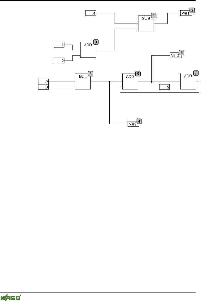
The following arrangement exists after selecting the command: x Sequence after the ordering according to data flow
WAGO-I/O-SYSTEM 759 WAGO-I/O-PRO 32
216 • The Editors
The Graphic Editors
When this command is selected the first thing to happen is that the elements are ordered topographically. A new sequential processing list is then created. Based on the known values of the inputs, the computer calculates which of the as yet not numbered elements can be processed next. In the above "network" the block AND, for example, could be processed immediately since the values at its inputs (1 and 2) are known. Block SUB can only then be processed since the result from ADD must be known first, etc.
Feedback paths are inserted last.
The advantage of the data flow sequencing is that an output box which is connected to the output of a block comes immediately after it in the data flow sequencing system which by topological ordering would not always be the case. The topological ordering can deliver another result in some cases than ordering by data flow, a point which one can recognise from the above example.
5.4.5.31'Extras' 'Create macro''
Symbol: 
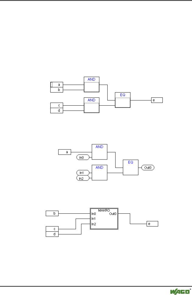
With this command, several POUs that are selected at the same time can be assembled into a block, which can be named as a macro. Macros only can be reproduced by Copy/Paste, whereby each copy becomes a separate macro whose name can be chosen independently. Macros are thus not references. All connections that are cut by the creation of a macro generate inor out-pins on the macro. Connections to inputs generate an in-pin. The default name appears
WAGO-I/O-SYSTEM 759 WAGO-I/O-PRO 32
The Editors • 217
The Graphic Editors
next to the pin in the form In<n>. For connections to outputs, Out<n> appears. Affected connections which had connection markers prior to the creation of the macro, retain the connection marker on the PIN of the macro.
At first, a macro has the default name "MACRO". This can be changed in the Name field of the macro use. If the macro is edited, the name of the macro will be displayed in the title bar of the editor window appended to the POU name.
Example:
Selection
Macro:
In the editor:
5.4.5.32'Extras' 'Jump into Macro'
Symbol: 
WAGO-I/O-SYSTEM 759 WAGO-I/O-PRO 32

218 • The Editors
The Graphic Editors
By this command, or by double clicking on the body of the macro, the macro is opened for editing in the editor window of the associated POU. The name of the macro is displayed appended to the POU name in the title bar.
The pin boxes generated for the inand outputs of the macro during creation can be handled like normal POU inand outputs. They can also be moved, deleted, added, etc. They differ only in how they are displayed and have no
position index. For adding you can use the buttons  (input) resp.
(output), which are available in the menu bar. Pin boxes have rounded corners. The text in the pin-box matches the name of the pin in the macro display.
The order of the pins in the macro box follows the order of execution of the elements of the macro. A lower order index before a higher one, higher pin before lower.
The processing order within the macro is closed, in other words the macro is processed as a block, at the position of the macro in the primary POU. Commands for manipulating the order of execution therefore operate only within the macro.
5.4.5.33'Extras' 'Expand macro'
With this command, the selected macro is re-expanded and the elements contained in it are inserted in the POU at the macro's location. The connections to the pins of the macro are again displayed as connections to the inor outputs of the elements. If the expansion of the macro can not occur at the location of the macro box for lack of space, the macro is displaced to the right and down until enough space is available.
Note:
If the project is saved under project version number 2.1, the macros will likewise all be expanded. All macros will also be expanded before conversion into other languages.
5.4.5.34'Extras' 'Back one macro level', 'Extras' 'Back all macro level'
Symbols: 
These commands are also available in the toolbar, as soon as a macro is opened for editing. If macros are nested within one another, it is possible to switch to the next higher or to the highest display level.
5.4.5.35Feedback paths in CFC
Feedback paths can only be displayed directly in the continuous function chart editor and not in the usual function block diagram editor. Here it should be observed that the output of a block always carries an internal intermediate variable. The data type of the intermediate variable results, for operators, from the largest data type of the inputs.
WAGO-I/O-SYSTEM 759 WAGO-I/O-PRO 32