Материал: m912201e

224 • Overview of the Resources
Global Variables
external variable list ! External variable lists only can be edited externally and they will be read at each opening and compiling of the project.
Syntax:
VAR_GLOBAL
(* Variables declarations *)
END_VAR
6.1.3.3 Editing Remanent Global Variables Lists
If they are supported by the runtime system, remanent variables may be processed. There are two types of remanent global variables:
Retain variables remain unchanged after an uncontrolled shutdown of the runtime system (off/on) or an 'Online' 'Reset' in WAGO-I/O-PRO 32. Persistent variables remain unchanged after a controlled shutdown of the runtime system (stop, start) or an 'Online' 'Cold reset' or a download.
Persistent variables are not automatically also Retain variables !
Remanent variables are additionally assigned the keyword RETAIN or
PERSISTENT.
Network variables are also defined in this syntax.
Syntax:
VAR_GLOBAL RETAIN
(* Variables declarations *)
END_VAR
VAR_GLOBAL PERSISTENT
(* Variables declarations *)
END_VAR
6.1.4 Global Constants
Global constants additionally get the keyword CONSTANT.
Syntax:
VAR_GLOBAL CONSTANT
(* Variables declarations *)
END_VAR
WAGO-I/O-SYSTEM 759 WAGO-I/O-PRO 32

Overview of the Resources |
• 225 |
Variable Configuration |
|
|
|
6.2 Variable Configuration
In function blocks it is possible to specify addresses for inputs and outputs that are not completely defined, if you put the variable definitions between the key words VAR and END_VAR. Addresses not completely defined are identified with an asterisk.
Example:
FUNCTION_BLOCK locio
VAR
loci AT %I*: BOOL := TRUE; loco AT %Q*: BOOL;
END_VAR
Here two local I/O-variables are defined, a local-In (%I*) and a local-Out (%Q*).
If you want to configure local I/Os for variables configuration in the Object Organizer in the Resources register card, the object Variable_Configuration will generally be available. The object then can be renamed and other objects can be created for the variables configuration.
The editor for variables configuration works like the declaration editor.
Variables for local I/O-configurations must be located between the key words
VAR_CONFIG and END_VAR.
The name of such a variable consists of a complete instance path through which the individual POUs and instance names are separated from one another by periods. The declaration must contain an address whose class (input/output) corresponds to that of the incompletely specified address (%I*, %Q*) in the function block. Also the data type must agree with the declaration in the function block.
Configuration variables, whose instance path is invalid because the instance does not exist, are also denoted as errors. On the other hand, an error is also reported if no configuration exists for an instance variable. In order to receive a list of all necessary configuration variables, the "All Instance Paths" menu item in the 'Insert' menu can be used.
x Example
Assume that the following definition for a function block is given in a program:
PROGRAM PLC_PRG
WAGO-I/O-SYSTEM 759 WAGO-I/O-PRO 32

226 • Overview of the Resources
Variable Configuration
VAR
Hugo: locio;
Otto: locio;
END_VAR
Then a corrected variable configuration would look this way:
VAR_CONFIG
PLC_PRG. Hugo.loci AT %IX1.0 : BOOL;
PLC_PRG. Hugo.loco AT %QX0.0 : BOOL;
PLC_PRG. Otto.loci AT %IX1.0 : BOOL;
PLC_PRG.Otto.loco AT %QX0.3 : BOOL;
END_VAR
6.2.1 ‚Insert' 'All Instance Paths'
With this command a VAR_CONFIG - END_VAR-block is generated that contains all of the instance paths available in the project. Declarations already on hand do not need to be reinserted in order to contain addresses already in existence. This menu item can be found in the window for configuration of variables if the project is compiled ('Project' 'Rebuild All').
6.2.2 Document Frame
6.2.2.1 Document Frame
If a project is to receive multiple documentations, perhaps with German and English comments, or if you want to document several similar projects that use the same variable names, then you can save yourself a lot of work by creating a docuframe with the 'Extras' 'Make Docuframe File' command.
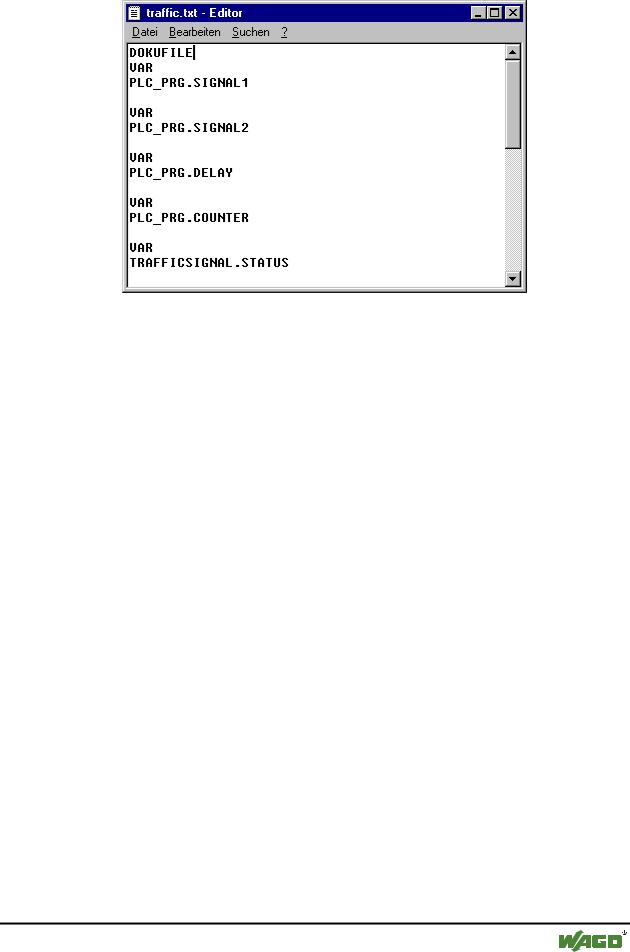
The created file can be loaded into a desired text editor and can be edited. The file begins with the DOCUFILE line. Then a listing of the project variables follows in an arrangement that assigns three lines to each variable: a VAR line that shows when a new variable comes; next, a line with the name of the variable; and, finally, an empty line. You can now replace this line by using a comment to the variable. You can simply delete any variables that you are unable to document. If you want, you can create several document frames for your project.
x Windows Editor with Document Frame
WAGO-I/O-SYSTEM 759 WAGO-I/O-PRO 32
Overview of the Resources |
• 227 |
PLC Browser |
|
|
|
In order to use a document frame, give the 'Extras' 'Link Docu File' command. Now if you document the entire project, or print parts of your project, then in the program text, there will be an insertion of the comment produced in the docuframe into all of the variables. This comment only appears in the printout!
6.2.2.2 'Extras' 'Make Docuframe File'
Use this command to create a document frame. The command is at your disposal, whenever you select an object from the global variables.
A dialog box will open for saving files under a new name. In the field for the name file, the *.txt extension has already been entered. Select a desired name. Now a text file has been created in which all the variables of your project are listed.
6.2.2.3 'Extras' 'Link Docu File'
With this command you can select a document frame.
The dialog box for opening files is opened. Choose the desired document frame and press OK. Now if you document the entire project, or print parts of your project, then in the program text there will be an insertion of the comment produced in the docuframe into all of the variables. This comment only appears in the printout!
To create a document frame, use the 'Extras' 'Make Docuframe File' command.
6.3 PLC Browser
The PLC-browser is a text-based control monitor (terminal). Commands for the request of specific information from the controller are entered in an entry line and sent as string to the controller. The returned response string is displayed in a result window of the browser. This functionality serves diagnosticand debugging purposes.
WAGO-I/O-SYSTEM 759 WAGO-I/O-PRO 32
228 • Overview of the Resources
PLC Configuration
The available comands and functions are depending on the target system
6.4 PLC Configuration
The  PLC Configuration is found as an object in the register card Resources in the Object Organizer. With the PLC Configuration editor, you can describe the I/O-modules connected to the hardware the opened project is established for. In WAGO-I/O-PRO 32 these entries are used for information and the selection of the connected controller is done with the menu Extras \ PLC Selection.
6.4.1 PLC Selection
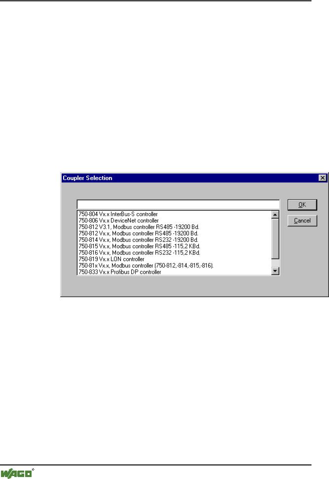
The selection of the connected controller is done with the menu Extras \ PLC Selection.
All available controllers are shown in a selection list. This list is shown automatically when you login without selecting a controller before.
The selection is accepted with OK or aborted with CANCEL.
6.5 Task Configuration
In addition to declaring the special PLC_PRG program, you can also control the processing of your project using the task management.
The  Task Configuration is found as an object in the Resources register card in the Object Organizer. The task editor contains a series of tasks. The task declaration consists of the name of the task, an entry for the priority the task is to have, and an entry for the condition under which the task is to be executed. This requirement can either be a time interval, according to which the task is to be executed, or a global variable, in the event it has a rising edge, brings about an execution.
WAGO-I/O-SYSTEM 759 WAGO-I/O-PRO 32