Материал: m912201e
Overview of the Resources |
• 229 |
Task Configuration |
|
|
|
For each task you can now specify a series of programs that will be started by the task. If the task is executed in the present cycle, then these programs will be processed the length of one cycle.
The Task Configuration is displayed in the following form:
The Task Configuration is located in the first line.
Underneath and indented from the Task Configuration, you will find a sequence of task entries (with name, priority, interval, and occurrence).
Below each task entry, there is again a series of program call ups.
x Example for a Task Configuration
In this example of a Task Configuration, Task2 has a lower priority than Task1. Task1, however, is only executed every two seconds. (The entry under Single is disregarded.) Thus, in this Task Configuration, Task1 is executed every two seconds, and, in between, Task2 can be executed at any time, provided that the global variable "Schalten" has a rising edge.
6.5.1Which task is being processed?
For the execution, the following rules apply:
That task is executed, whose condition has been met; i.e., its specified time has expired, or after its condition variable exhibits a rising edge.
If several tasks have a valid requirement, then the task with the highest priority will be executed.
If several tasks have valid conditions and equivalent priorities, then the task that has had the longest waiting time will be executed first.
The most important commands are found in the context menu (right mouse button or <Ctrl>+<F10>).
6.5.2Working in the Task Configuration
At the heading of the Task Configuration are the words "Task Configuration." If a plus sign is located before the words, then the sequence list is closed. By doubleclicking on the list or pressing <Enter>, you can open the list. A minus sign now appears. By doubleclicking once more, you can close the list again.
For every task, there is a list of program call-ups attached. Likewise, you can open and close this list the same way.
With the 'Insert' 'Insert Task' command, you can insert a task.
With the 'Insert' 'Insert Program Call', a program call will be inserted.
WAGO-I/O-SYSTEM 759 WAGO-I/O-PRO 32
230 • Overview of the Resources
Task Configuration
With the 'Extras' 'Edit Entry' command, you can edit the task characteristics or the program call-up, depending on the selected element.
By clicking on the task or program name, or by pressing the <Space bar>, you can set an edit control box around the name. Then you can change the designation directly in the task editor.
6.5.3'Insert' 'Insert Task' or 'Insert' 'Append Task'
With this command you can insert a new task into the Task Configuration.
If a task is selected, then the 'Insert Task' command will be at your disposal. The new task will be inserted in front of the cursor. If the words Task Configuration are selected, then the 'Append Task' is available, and the new task will be appended to the end of the existing list.
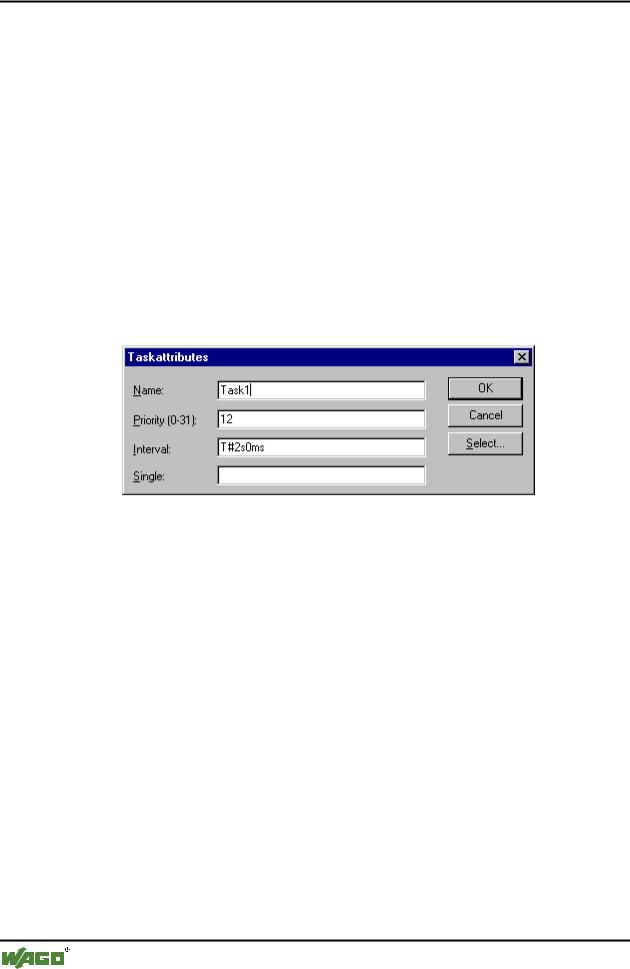
The dialog box will open for you to set the task attributes.
x Dialog Box for Setting Task Attributes
In the dialog box you can enter the desired attributes: the Name; the Priority (a number between 0 and 31, with the following validities: 0 has the highest, and, 31, the lowest priority); the Interval after which the task should be started again; or a variable that, following a raising edge, will cause an execution of the task (in the Single field). With the Select... button, you can open the Input Assistant to select from the declared variables.
If an entry is on hand for both the interval and for the variable, then only the interval time will be considered for the execution requirement. If an entry has not been made in either of the two fields, then the execution intervall is depending on which target system is used (see the specific runtime system documentation; e.g. an interval of 10 ms is set by the runtime WAGO-I/O- PRO 32SP NT V2.2).
6.5.4 'Insert' 'Insert Program Call' or 'Insert' 'Append Program Call'
With these commands you will open the dialog box for entering a program call to a task in the Task Configuration.
With 'Insert Program Call', the new program call is inserted in front of the cursor, and with 'Append Program Call', the program call is appended to the end of the existing list.
WAGO-I/O-SYSTEM 759 WAGO-I/O-PRO 32
Overview of the Resources |
• 231 |
Sampling Trace |
|
|
|
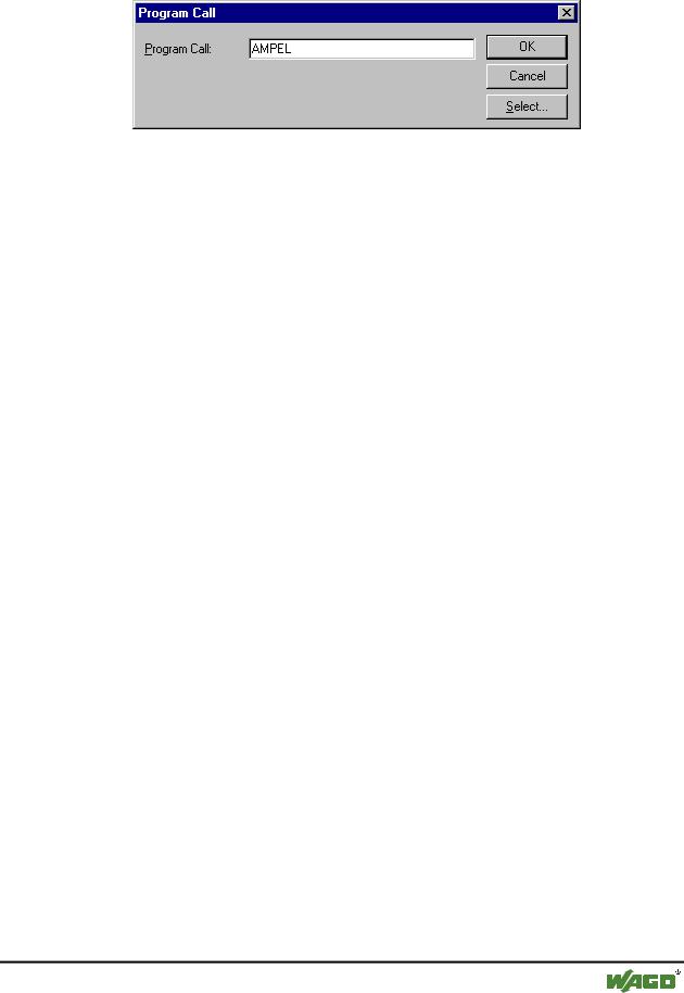
x Dialog box for Program Call Entry
In the field, specify a valid program name for your project, or open the Input Assistant with the Select button to select a valid program name. If the selected program requires input variables, then enter these in their usual form and of the declared type (for example, prg(invar:=17)).
6.5.5 'Extras' 'Edit Entry'
Depending on the element selected, you can use this command in the Task Configuration to open either the dialog box for setting the task attributes (see 'Insert' 'Task') or the dialog box for entering the program call (see 'Insert' 'Program Call').
If the cursor is located at the task entry, and there is no list of program calls appended to the task entry, then you open the dialog for setting the doubleclicking on the entry or by pressing <Enter>.
If the cursor is located on an entry for a program call, then you can also open the dialog box for editing the program entry by doubleclicking on the entry.
By clicking on the task or program name, or by pressing the <Space bar>, you can set an edit control box around the name. Then, you can change the designation directly in the task editor.
6.5.6 'Extras' 'Set Debug Task'
With this command a debugging task can be set in Online mode in the Task Configuration. The text [DEBUG] will appear after the set task.
The debugging capabilities apply, then, only to this task. In other words, the program only stops at a breakpoint if the program is gone through by the set task.
6.6 Sampling Trace
Sample tracing means that the progression of values for variables is traced over a certain time frame. These values are written in a ring buffer (trace buffer). If the memory is full, then the "oldest" values from the start of the memory will be overwritten. As a maximum, 20 variables can be traced at the same time. A maximum of 500 values can be traced per variable.
WAGO-I/O-SYSTEM 759 WAGO-I/O-PRO 32

232 • Overview of the Resources
Sampling Trace
Since the size of the trace buffer in the PLC has a fixed value, in the event of very many or very wide variables (DWORD), fewer than 500 values can be traced.
Example: if 10 WORD variables are traced and if the memory in the PLC is 5000 bytes long, then, for every variable, 250 values can be traced.
In order to be able to perform a trace, open the object for a  Sampling Trace in the Resources register card in the Object Organizer. After this, you must enter the trace variables to be traced. (See 'Extras' 'Trace Configuration'.) After you have sent the configuration with 'Save Trace' to the PLC and have started the trace in the PLC ('Start Trace'), then the values of the variables will be traced. With 'Read Trace', the final traced values will be read out and displayed graphically as curves.
6.6.1 'Extras' 'Trace Configuration'
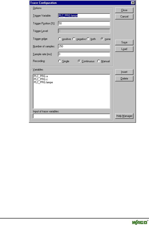
With this command you will be given the dialog box for entering the variables to be traced, as well as diverse trace parameters for the Sampling Trace. The dialog can also be opened by a double click in the grey area of the dialog Sampling Trace.
x Dialog Box for Trace Configuration
WAGO-I/O-SYSTEM 759 WAGO-I/O-PRO 32
Overview of the Resources |
• 233 |
Sampling Trace |
|
|
|
The list of the Variables to be traced is initially empty. In order to append a variable the variable must be entered in the field under the list. Following this, you can use the Add button or the <Enter> to append the variable to the list. You can also use the Input Assistant.
A variable is deleted from the list when you select the variable and then press the Delete button.
A Boolean or analogue variable can be entered into the field Trigger Variable. The input assistance can also be used here. The trigger variable describes the termination condition of the trace. In Trigger Level you enter the level of an analogue trigger variable at which the trigger event occurs. When Trigger edge positive is selected the trigger event occurs after an ascending edge of the Boolean trigger variable or when an analogue variable has passed through the trigger level from below to above. Negative causes triggering after a descending edge or when an analogue variable went from above to below. Both causes triggering for both descending and ascending edges or by a positive or negative pass, whereas none does not initiate a triggering event at all. Trigger Position is used to set the percentage of the measured value which will be recorded before the trigger event occurs. If, for example, you enter 25 here then 25 % of the measured values are shown
WAGO-I/O-SYSTEM 759 WAGO-I/O-PRO 32