Материал: m912201e

184 • The Editors
The Graphic Editors
With this command, operators, functions, function blocks and programs can be inserted. First of all, it is always inserted an "AND" operator. This can be converted by Selection and Overwrite of the type text ("AND") into every other operator, into every function, into every function block and every program. You can select the desired POU by using Input Assistant (<F2>). If the new selected block has another minimum number of inputs, these will be attached. If the new block has a smaller highest number of inputs, the last inputs will be deleted.
In functions and function blocks, the formal names of the inand outputs are displayed.
In function blocks there exists an editable instance field above the box. If another function block that is not known is called by changing the type text, an operator box with two inputs and the given type is displayed. If the instance field is selected, Input Assistant can be obtained via <F2> with the categories for variable selection.
The newest POU is inserted at the selected position:
If an input is selected (Cursor Position 2), then the POU is inserted in front of this input. The first input of this POU is linked to the branch on the left of the selected input. The output of the new POU is linked to the selected input.
If an output is selected (Cursor Position 4), then the POU is inserted after this output. The first input of the POU is connected with the selected output. The output of the new POU is linked to the branch with which the selected output was linked.
If a POU, a function, or a function block is selected (Cursor Position 3), then the old element will be replaced by the new POU.
As far as possible, the branches will be connected the same way as they were before the replacement. If the old element had more inputs than the new one, then the unattachable branches will be deleted. The same holds true for the outputs.
If a jump or a return is selected, then the POU will be inserted before this jump or return. The first input of the POU is connected with the branch to the left of the selected element. The output of the POU is linked to the branch to the right of the selected element.
If the last cursor position of a network is selected (Cursor Position 6), then the POU will be inserted following the last element. The first input of the POU is linked to the branch to the left of the selected position.
All POU inputs that could not be linked will receive the text "???". This text must be clicked and changed into the desired constant or variable.
If there is a branch to the right of an inserted POU, then the branch will be assigned to the first POU output. Ansonsten bleiben die Ausgänge unbelegt.
5.4.2.7 'Insert' 'Input'
Symbol: |
Shortcut: <Ctrl>+<U> |
WAGO-I/O-SYSTEM 759 WAGO-I/O-PRO 32

The Editors • 185
The Graphic Editors
This command inserts an operator input. With many operators, the number of inputs may vary. (For example, ADD can have 2 or more inputs.)
In order to extend such an operator by an input, you need to select the input in front of which you wish to insert an additional input (Cursor Position 1); or you must select the operator itself (Cursor Position 3), if a lowest input is to be inserted (see 'Cursor positions in FBD').
The inserted input is allocated with the text "???". This text must be clicked and changed into the desired constant or variable. For this you can also use the Input Assistant.
5.4.2.8 'Insert' 'Output'
Symbol: 
This command inserts an additional assignment into an existing assignment. This capability serves the placement of so-called assignment combs; i.e., the assignment of the value presently located at the line to several variables.
If you select the lined cross above an assignment (Cursor Position 5) (see 'Cursor positions in FBD') or the output directly in front of it (Cursor Position 4), then there will be another assignment inserted after the ones already there.
If the line cross directly in front of an assignment is selected (Cursor Position 4), then another assignment will be inserted in front of this one.
The inserted output is allocated with the text "???". This text must be clicked and changed into the desired variable. For this you can also use the Input Assistant.
5.4.2.9 'Extras' 'Negate
Symbol: |
Shortcut: <Ctrl>+<N> |
With this command you can negate the inputs, outputs, jumps, or RETURN instructions. The symbol for the negation is a small circle at a connection.
If an input is selected (Cursor Position 2) (see 'Cursor positions in FBD'), then this input will be negated.
If an output is selected (Cursor Position 4), then this output will be negated.
If a jump or a return is marked, then the input of this jump or return will be negated.
A negation can be canceled through renewed negation.
WAGO-I/O-SYSTEM 759 WAGO-I/O-PRO 32
186 • The Editors
The Graphic Editors
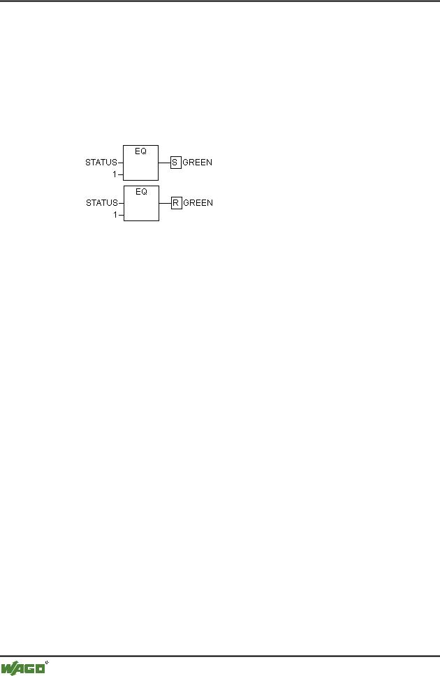
5.4.2.10'Extras' 'Set/Reset'
Symbol: 
With this command you can define outputs as Set or Reset Outputs. A grid with Set Output is displayed with [S], and a grid with Reset Output is displayed with [R].
x Set/Reset Outputs in FBD
An Output Set is set to TRUE, if the grid belonging to it returns TRUE. The output now maintains this value, even if the grid jumps back to FALSE.
An Output Reset is set to FALSE, if the grid belonging to it returns FALSE. The output maintains its value, even if the grid jumps back to FALSE.
With multiple executions of the command, the output will alternate between set, reset, and normal output.
5.4.2.11Cutting, Copying, Pasting, and Deleting in FBD
The commands used to 'Cut', 'Copy', 'Paste', and 'Delete' are found under the 'Edit' menu item.
If a line cross is selected(Cursor Position 5) (see 'Cursor positions in FBD'), then the assignments, jumps, or RETURNS located below the crossed line will be cut, deleted, or copied.
If a POU is selected (Cursor Position 3), then the selected object itself, will be cut, deleted, or copied, along with all of the branches dependent on the inputs, with the exception of the first (highest position) branch.
Otherwise, the entire branch located in front of the cursor position will be cut, deleted, or copied.
After copying or cutting, the deleted or copied part is located on the clipboard and can now be pasted, as desired.
In order to do so, you must first select the pasting point. Valid pasting points include inputs and outputs.
WAGO-I/O-SYSTEM 759 WAGO-I/O-PRO 32

The Editors • 187
The Graphic Editors
If a POU has been loaded onto the clipboard (As a reminder: in this case all connected branches except the first are located together on the clipboard), the first input is connected with the branch before the pasting point.
Otherwise, the entire branch located in front of the pasting point will be replaced by the contents of the clipboard.
In each case, the last element pasted is connected to the branch located in front of the pasting point.
Note:
The following problem is solved by cutting and pasting: A new operator is inserted in the middle of a network. The branch located on the right of the operator is now connected with the first input, but should be connected with the second input. You can now select the first input and perform the command 'Edit' 'Cut'. Following this, you can select the second input and perform the command 'Edit' 'Paste'. This way, the branch is dependent on the second input.
5.4.2.12The Function Block Diagram in the Online Mode
In the Function Block Diagram, breakpoints can only be set to networks. If a breakpoint has been set to a network, then the network numbers field will be displayed in blue. The processing then stops in front of the network where the breakpoint is located. In this case, the network numbers field will become red. Using stepping (single step), you can jump from network to network.
The current value is displayed for each variable. Exception: If the input to a function block is an expression, only the first variable in the expression is monitored.
Doubleclicking on a variable opens the dialog box for writing a variable. Here it is possible to change the present value of the variable. In the case of Boolean variables, no dialog box appears; these variables are toggled.
The new value will turn red and will remain unchanged. If the 'Online' 'Write values' command is given, then all variables are placed in the selected list and are once again displayed in black.
The flow control is started with the 'Online' 'Flow control' command Using the flow control, you can view the present values that are being carried in the networks over the connecting lines. If the connecting lines do not carry Boolean values, then the value will be displayed in a specially inserted field. If the lines carry Boolean values, then they will be shaded blue in the event that they carry TRUE. By this means, you can accompany the flow of information while the PLC is running.
If you place the mouse pointer briefly above a variable, then the type, the address and the comment about the variable will be displayed in a Tooltip.
WAGO-I/O-SYSTEM 759 WAGO-I/O-PRO 32
188 • The Editors
The Graphic Editors
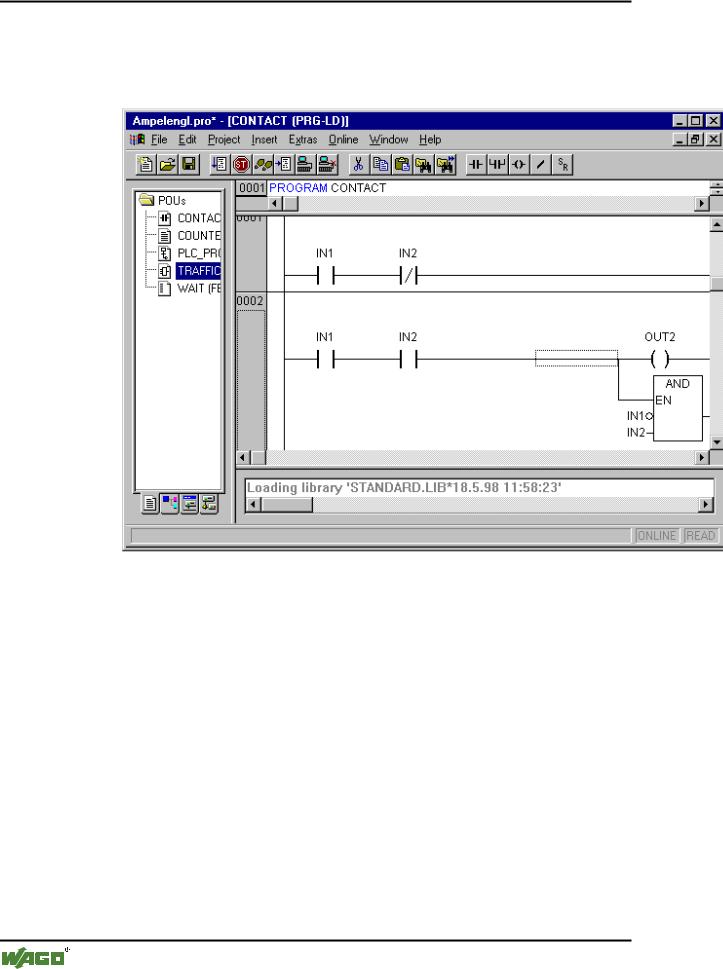
5.4.3 The Ladder Editor
This is how a POU written in the LD appears in the WAGO-I/O-PRO 32 editor:
All editors for POUs consist of a declaration part and a body. These are separated by a screen divider.
The LD editor is a graphic editor. The most important commands are found in the context menu (right mouse button or <Ctrl>+<F10>).
For information about the elements, see Ladder Diagram (LD).
5.4.3.1 Cursor Positions in the LD Editors
The following locations can be cursor positions, in which the function block and program accessing can be handled as contacts. POUs with EN inputs and other POUs connected to them are treated the same way as in the Function Block Diagram. Information about editing this network part can be found in the chapteron the FBD Editor.
1. Every text field (possible cursor positions framed in black)
WAGO-I/O-SYSTEM 759 WAGO-I/O-PRO 32