Материал: m912201e
The Editors • 179
The Graphic Editors
5.4.1.1 Zoom
Objects such as POUs, actions, transitions etc. in the languages SFC, LD, FBD, CFC and in visualizations can be enlarged or reduced in size with a zoom function. All elements of the window contents of the implementation part are affected; the declaration part remains unchanged.
In standard form, every object is displayed with the zoom level 100%. The zoom level that is set is saved as an object property in the project.
The printing of project documentation always occurs at the 100% display level!
The zoom level can be set through a selection list in the toolbar. Values between 25% and 400% can be selected; individual values between 10% and 500% can be entered manually.
The selection of a zoom level is only available if the cursor rests on an object created in a graphical language or a visualization object.
Even with the object zoomed, cursor positions in the editors can be further selected and even reached with the arrow keys. Text size is governed by the zoom factor and the font size that is set.
The execution of all editor menu features (e.g. inserting a box) as a function of cursor position is available at all zoom levels, taking the same into account.
In Online mode, each object is displayed according to the zoom level that has been set; Online functionality is available without restriction.
When the IntelliMouse is used, an object can be enlarged/reduced by pressing the <CTRL> key and at the same time turning the wheel forward or backwards.
5.4.1.2 Network
In the LD and FBD editors, the program is arranged in a list of networks. Each network is designated on the left side by a serial network number and has a structure consisting of either a logical or an arithmetic expression, a program, function or function block call, and a jump or a return instruction.
5.4.1.3 Label
Each network has a label that can optionally be left empty. This label is edited by clicking the first line of the network, directly next to the network number. Now you can enter a label, followed by a colon.
5.4.1.4 Network Comments,'Extras' 'Options'
Every network can be supplied with a multi-lined comment. In 'Extras' 'Options', you can enter the maximum number of lines to be made available
WAGO-I/O-SYSTEM 759 WAGO-I/O-PRO 32

180 • The Editors
The Graphic Editors
for a network comment. This entry is made in the maximum comment size field. (The default value here is 4.) You can also enter the number of lines that generally should be reserved for comments (minimum comment size). If, for example, the number 2 is entered, then, at the start of each network there will be two empty lines after the label line. The default value here is 0, which has the advantage of allowing more networks to fit in the screen area.
If the minimal comment size is greater than 0, then in order to enter a comment you simply click in the comment line and then enter the comment. Otherwise you must next select the network to which a comment is to be entered, and use 'Insert' 'Comment' to insert a comment line. In contrast to the program text, comments are displayed in gray.
5.4.1.5 'Insert' 'Network (after)' or 'Insert' "Network (before)"
Shortcut: <Shift>+<T>
In order to insert a new network in the FBD or the LD editor, select the 'Insert' 'Network (after)' or the 'Insert' 'Network (before)' command, depending on whether you want to insert the new network before or after the present network. The present network can be changed by clicking the network number. You will recognize it in the dotted rectangle under the number. With the <Shift key> and a mouse click you can select from the entire area of networks, from the present one to the one clicked.
5.4.1.6 The network editors in the online mode
In the FBD and the LD editors you can only set breakpoints for networks. The network number field of a network for which a breakpoint has been set, is displayed in blue. The processing then stops in front of the network, where the breakpoint is located. In this case, the network number field is displayed in red. With single step processing (steps), you can jump from network to network.
All values are monitored upon entering and exiting network POUs (Program Organization Units).
The following should be noted when monitoring expressions or Bit-addressed variables: In expressions, e.g. a AND b, used as transition condition or function block input, the value of the whole expression is always displayed (a AND b is shown in blue or as :=TRUE, if a and b are TRUE). For Bitaddressed variables, the bit value that is addressed is always monitored (e.g. a.3 is displayed in blue or with ":=TRUE, if a has the value 4)
The flow control is run with the 'Online' 'Flow control' command. Using the flow control, you can view the present values that are being carried in the networks over the connecting lines. If the connecting lines do not carry Boolean values, then the value will be displayed in a specially inserted field. The monitor fields for variables that are not used (e.g. in the function SEL) are displayed in a shade of grey. If the lines carry Boolean values, then they will
WAGO-I/O-SYSTEM 759 WAGO-I/O-PRO 32
The Editors • 181
The Graphic Editors
be shaded blue, in the event that they carry TRUE. Therefore, you can accompany the flow of information while the PLC is running.
If you place the mouse pointer briefly above a variable, then the type, the address and the comment about the variable will be displayed in a Tooltip.
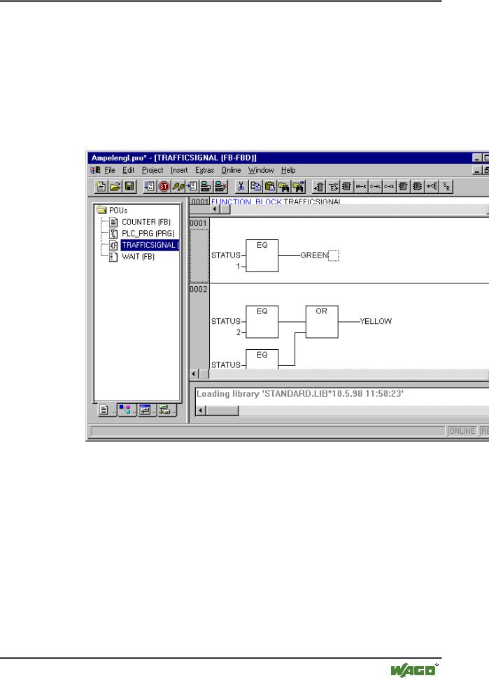
5.4.2 The Function Block Diagram Editor
This is how a POU written in the FBD under the corresponding WAGO-I/O- PRO 32 editor looks:
The Function Block Diagram editor is a graphic editor. It works with a list of networks, in which every network contains a structure that displays, respectively, a logical or an arithmetical expression, the calling up of a function block, a function, a program, a jump, or a return instruction.The most important commands are found in the context menu (right mouse button or <Ctrl>+<F10>).
5.4.2.1 Cursor positions in FBD
Every text is a possible cursor position. The selected text is on a blue background and can now be changed.
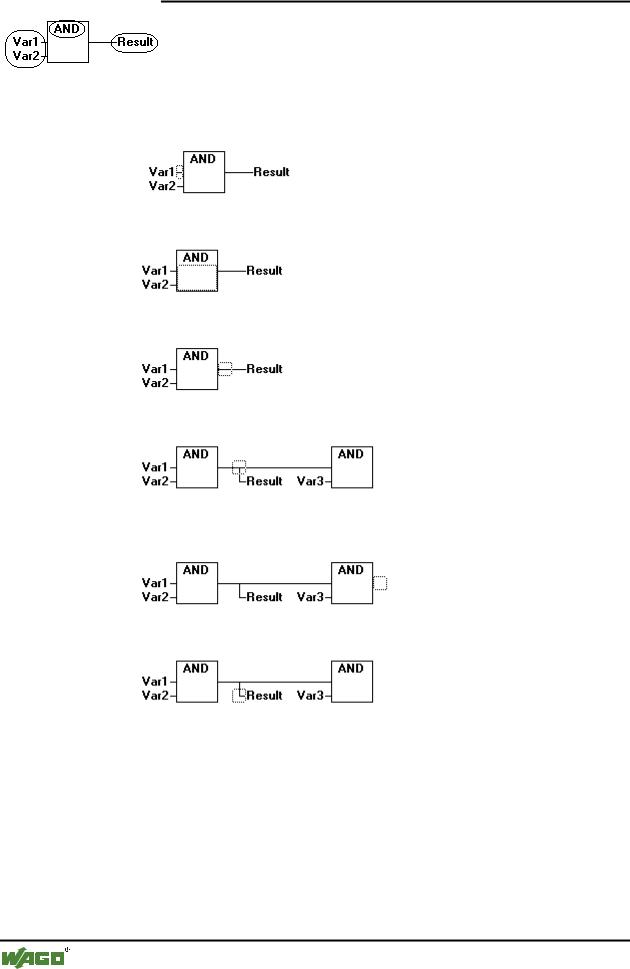
You can also recognize the present cursor position by a dotted rectangle. The following is a list of all possible cursor positions with an example:
1) Every text field (possible cursor positions framed in black):
WAGO-I/O-SYSTEM 759 WAGO-I/O-PRO 32
182 • The Editors
The Graphic Editors
2)Every input:
3)Every operator, function, or function block:
4)Outputs, if an assignment or a jump comes afterward:
5)The lined cross above an assignment, a jump, or a return instruction:
6)Behind the outermost object on the right of every network ("last cursor position," the same cursor position that was used to select a network):
7)The lined cross directly in front of an assignment:
5.4.2.2How to set the cursor in FBD
The cursor can be set at a certain position by clicking the mouse, or with the help of the keyboard.
Using the arrow keys, you can jump to the nearest cursor position in the selected direction at any time. All cursor positions, including the text fields, can be accessed this way. If the last cursor position is selected, then the <up> or <down> arrow keys can be used to select the last cursor position of the previous or subsequent network.
WAGO-I/O-SYSTEM 759 WAGO-I/O-PRO 32
The Editors • 183
The Graphic Editors
An empty network contains only three question marks "???". By clicking behind these, the last cursor position is selected.
5.4.2.3 'Insert' 'Assign' in FBD
Symbol: |
Shortcut: <Ctrl>+<A> |
This command inserts an assignment.
Depending on the selected position (see 'Cursor positions in FBD'), insertion takes place directly in front of the selected input (Cursor Position 2), directly after the selected output (Cursor Position 4) or at the end of the network (Cursor Position 6).
For an inserted assignment, a selection can be made accompanying the entered text "???", and the assignment can be replaced by the variable that is to be assigned. For this you can also use the Input Assistant.
In order to insert an additional assignment to an existing assignment, use the 'Insert' 'Output' command.
5.4.2.4 'Insert' 'Jump' in FBD
Symbol: |
Shortcut: <Ctrl>+<L> |
This command inserts a jump.
Depending on the selected position (see 'Cursor positions in FBD'), insertion takes place directly in front of the selected input (Cursor Position 2), directly after the selected output (Cursor Position 4) or at the end of the network (Cursor Position 6).
For an inserted jump, a selection can be made accompanying the entered text "???", and the jump can be replaced by the label to which it is to be assigned.
5.4.2.5 'Insert' 'Return' in FBD
Symbol: |
Shortcut: <Ctrl>+<R> |
This command inserts a RETURN instruction.
Depending on the selected position (see 'Cursor positions in FBD'), insertion takes place directly in front of the selected input (Cursor Position 2),directly after the selected output (Cursor Position 4), directly before the selected line cross (Cursor Position 5), or at the end of the network (Cursor Position 6)
5.4.2.6 'Insert' 'Box' in FBD
Symbol: |
Shortcut: <Ctrl>+<B> |
WAGO-I/O-SYSTEM 759 WAGO-I/O-PRO 32