Материал: m013800e

Внимание! Если размещение файла нарушает Ваши авторские права, то обязательно сообщите нам

Supply modules

PN750-601, 602, 609, 610, 611, 612, 613, 615

Technical Description

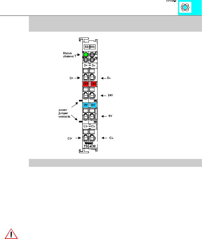
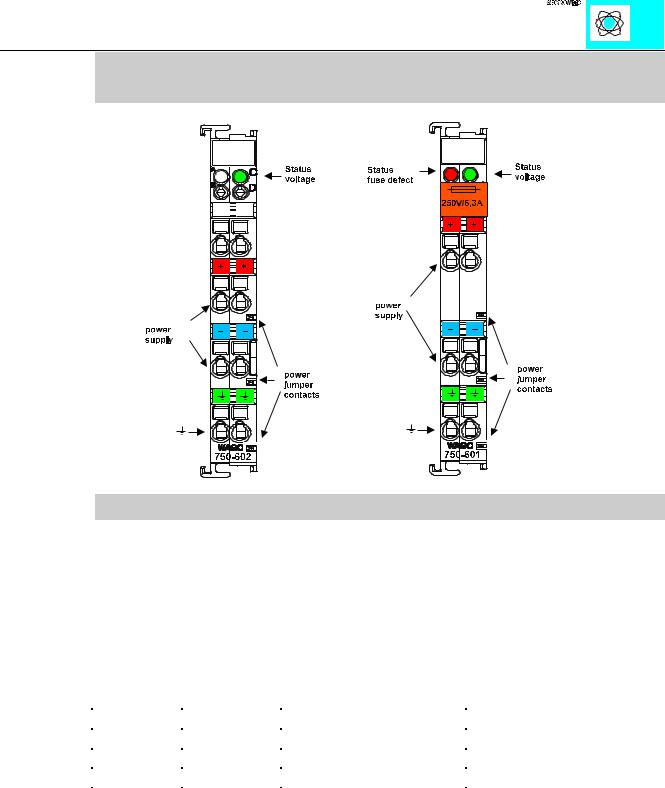
The supply module provides I/O module power through the power jumper contacts. Maximum current supply to all connected modules is 10 A. Maximum current supply to the modules with fuse holder is 6.3 A. Should higher currents be necessary, intermediate supply modules may be added in the assembly.

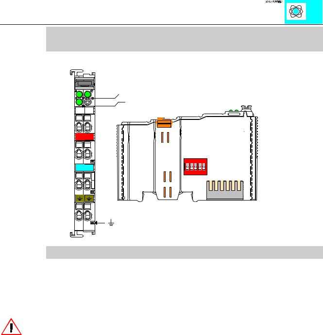
The modules 750-601, 609, 615, 610 and 611 are additionally equipped with a fuse holder. The change of the fuse is very easy by drawing out the fuse holder and changing the fuse. A blown fuse is indicated by a LED.

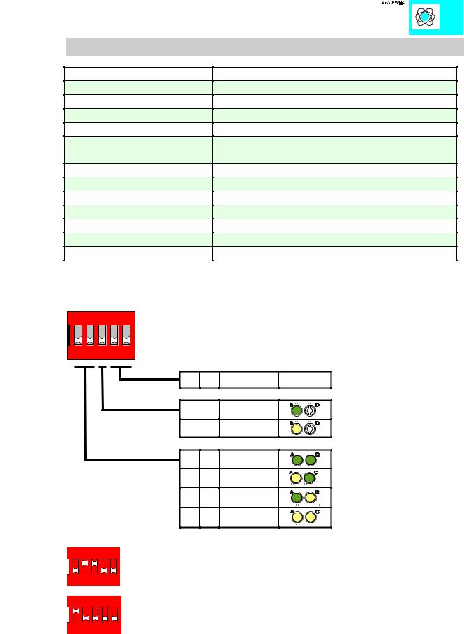
The modules 750-610 and 611 send information about the status of the supply module to the fieldbus coupler through two input bits.

Bit1

Bit2

Description

0

0

voltage < 15 V DC

1

0

fuse blown

0

1

fuse o.k., voltage o.k.

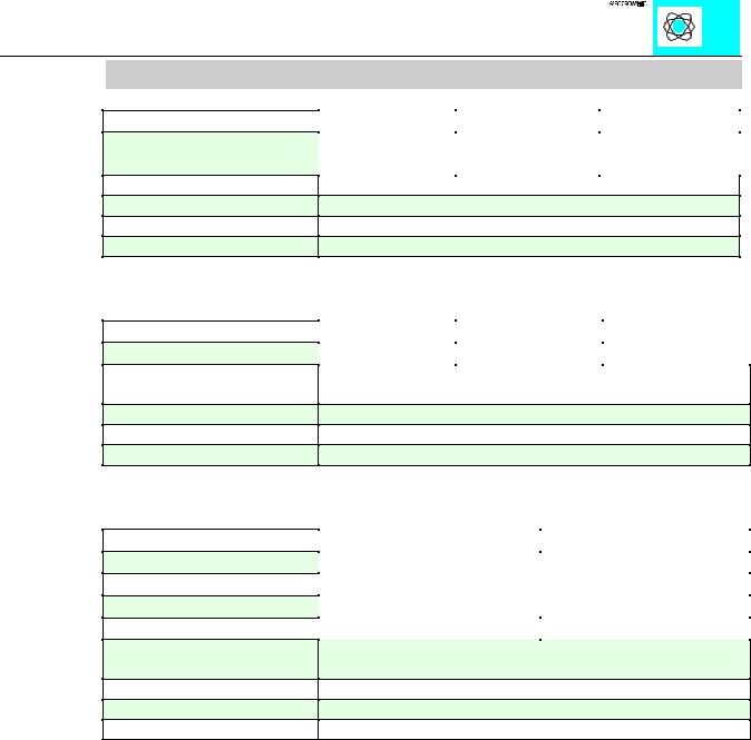
Using the supply modules you have to look for the allowed voltage. The following table shows the voltage for the supply modules.

The supply module 750-613 supplies the field side and te internal databus system voltage. The internal system voltage can supply 2 A max. If the sum of the internal current consumption exceeds 2 A, an additional supply module must be added.

Supply modules 750-601,602, 609,615,610,611,613

1

:$*2Ç, 2Ç6<67(0

Technical Data:

Item Number 750-

Voltage

Current via contacts

Operating temperature

Wire connection

Dimensions (mm) W x H x L

602

612

613

24 V DC

0 - 230 V AC/DC

24 V DC


(-15%/+20%)

max. 10 A

0 °C ... + 55 °C

CAGE CLAMP; 0,08 to 2,5 mm²

12 x 64 x 100, (from the upper edge of the carrier rail)

internal current 750-613: max. 2 A

Item Number 750-

Voltage

Current via contacts

Fuse

Operating temperature

Wire connection

Dimensions (mm) W x H x L

601

609

615

24 V DC

230 V AC

120 V AC

max. 6.3 A 5 x 20, 6.3 A

0 °C ... + 55 °C

CAGE CLAMP; 0,08 to 2,5 mm²

12 x 64 x 100, (from the upper edge of the carrier rail)

Item Number 750-

Number of inputs

Current consumption

Internal bitwidth

Voltage

Current via contacts

Fuse

Operating temperature

Wire connection

Dimensions (mm) W x H x L

610


611


2


5 mA


2


24 V DC


230 V AC

max. 6.3 A 5 x 20, 6.3 A

0 °C ... + 55 °C

CAGE CLAMP; 0,08 to 2,5 mm²

12 x 64 x 100, (from the upper edge of the carrier rail)

Supply modules 750-601,602, 609,615,610,611,613

2

:$*2Ç, 2Ç6<67(0

Binary spacer module

PN 750-622

1XPEHU RI LQSXWV RU RXWSXWV ,QSXWV RU 2XWSXWV

9

:$*2 9

ON

1 2 3 4 5

Technical description

The binary spacer module reserves bit-addresses in the WAGO buscoupler.

The number of in or outputs can be chosen by two DIP switches. 2, 4, 6 or 8 bits are possible (1, 2, 3 or 4-channel modules). A third DIP Switch chooses inputs or outputs. The kind of configuration is indicated by means of 3 LEDs even if there is no voltage applied.

The binary spacer module works like a supply module. The power supply must be made for the following modules.

Binary spacer module 750-622

1


:$*2 , 2 6<67(0

Technical Data

Item number 750-

Number of inor outputs

Nominal voltage

Internal current consumption

Voltage (field side)

Current via power jumper contacts

Input current (field side)

Isolation

Internal bit width

Configuration

Operating temperature

Wire connection

Dimensions (mm) WxHxL

622

2, 4, 6 or 8

5 V DC internal

10 mA max.

24 V DC (-15%/+20%)

10 A max.

-

500 V system/power supply

2, 4, 6 oder 8

none, optional via software parameter

0°C....+55°C

CAGE CLAMP; 0.08 to 2.5mm2

12 x 64* x 100 (*from upper edge of the carrier rail)

The DIP switches and LEDs are used as follows. When the switch is OFF the LED is also OFF (dark green symbol). When the switch is ON the LED lightens (yellow symbol).

ON

1 2 3 4 5

;;

2))

21

2)) 2)) 21 2)) 2)) 21 21 21

'RQ·W FDUH

,QSXWV

2XWSXWV

%LW [ %LW

%LW [ %LW

%LW [ %LW

%LW [ %LW

Examples:


ON


1

2

3

4

5

6 binary outputs (3x 2-channel output modules)


ON


1

2

3

4

5

4 binary inputs (2x 2-channel input modules)


Binary spacer module 750-622

2


:$*2 , 2 6<67(0

SSI Encoder Interface

PN 750-630, 750-630/000-001, 750-630/000-006

Technical Description:

This technical description is only valid for hardware and software versions

X X X X 2 B 0 2----. The product series number is printed on the right side of the module.

The operational mode of the module is factory preset to discern a 24 bit absolute encoder Graycode signal transmitted at 125kHz.

The following description is preliminary and is applicable to the factory configuration.

Attention:

The lowest power jumper contact is not carried out for some modules (e.g. 4-channel)! A module which needs all contacts (e.g. 2 channel digital) may not be connected to the right hand side of modules which do not have 3 power jumper contacts (e.g. 4 channel modules).

The SSI Interface is able to run with all WAGOÇI/OÇSYSTEM bus-couplers (except for the economy type).

SSI encoder 750-630

1

:$*2Ç, 2Ç6<67(0