Материал: m013800e

Technical Data
Item Number |
750-476 |
|
|
750-478 |
|
750-476/000-200 |
|
750-478/000-200 |
|
Number of channels |
|
2 |
|
|
Nominal voltage |
via system voltage (DC/DC) |
|||
Overvoltage resistance |
|
24 V max. |
|
|
Internal current |
|
75 mA typ. |
|
|
consumption |
|
|
|
|
Input signal |
+/- 10 V |
|
|
0 - 10 V |
Input impedance |
|
130 kΩ typ. |
|
|
Overvoltage protection |
24 V protected against polarity reversal |
|||
Resolution |
|
15 Bit + sign |
||
Input filter |
|
50 Hz |
|
|
Noise rejection at sampling |
|
< -100 dB |
|
|
frequency |
|
|
|
|
Noise rejection below |
|
< -40 dB |
|
|
sampling frequency |
|
|
|
|
Transition frequency |
|
13 Hz |
|
|
Isolation |
500 V system/power supply |
|||
Wandlungszeit |
|
80 ms typ. |
|
|
Bitwidth per channel |
|
16Bit: Data; |
|
|
|
optional 8Bit: control/status |
|||
Configuration |
none, optional via software parameter |
|||
Operating temperature |
|
0°C....+55°C |
|
|
Wire connection |
CAGE CLAMP; 0,08 bis 2,5mm2 |
|||
Dimensions (mm)WxHxL |
12 x 64* x 100 |
* from upper edge of the carrier rail |
||
Analog Inputs 750-476, 478 |
3 |
4;13614<<< |
:$*2®,22®6<67(0 |

The numerical format
All analog values will be shown in a unit numerical format. The resolution for 750-476 and 750-478 is 15 Bit plus sign.
750-476, -478
Input voltage |
Value |
|
|
Status |
LED |
|
0-10V |
±10V |
Binary |
Hex. |
Dec. |
(hex) |
error |
|
|
|
|
|
|
I (1,2) |
>11 |
>11 |
0111 1111 1111 1111 |
0x7FFF |
32767 |
0x42 |
on |
|
|
|
|
|
|
|
>10,5 |
>10,5 |
0111 1111 1111 1111 |
0x7FFF |
32767 |
0x42 |
off |
|
|
|
|
|
|
|
10 |
10 |
0111 1111 1111 1111 |
0x7FFF |
32767 |
0x00 |
off |
|
|
|
|
|
|
|
5 |
5 |
0100 0000 0000 0000 |
0x4000 |
16384 |
0x00 |
off |
|
|
|
|
|
|
|
2,5 |
2,5 |
0010 0000 0000 0000 |
0x2000 |
8192 |
0x00 |
off |
|
|
|
|
|
|
|
1,25 |
1,25 |
0001 0000 0000 0000 |
0x1000 |
4096 |
0x00 |
off |
|
|
|
|
|
|
|
0,0781 |
0,0781 |
0000 0001 0000 0000 |
0x0100 |
256 |
0x00 |
off |
|
|
|
|
|
|
|
0,049 |
0,049 |
0000 0000 0001 0000 |
0x0010 |
16 |
0x00 |
off |
|
|
|
|
|
|
|
0,0003 |
0,0003 |
0000 0000 0000 0001 |
0x0001 |
1 |
0x00 |
off |
|
|
|
|
|
|
|
0 |
0 |
0000 0000 0000 0000 |
0x0000 |
0 |
0x00 |
off |
|
|
|
|
|
|
|
<-0,5 |
|
0000 0000 0000 0000 |
0x0000 |
0 |
0x41 |
off |
|
|
|
|
|
|
|
<-1 |
|
0000 0000 0000 0000 |
0x0000 |
0 |
0x41 |
on |
|
|
|
|
|
|
|
|
-5 |
1100 0000 0000 0000 |
0xC000 |
49152 |
0x00 |
off |
|
|
|
|
|
|
|
|
-10 |
1000 0000 0000 0000 |
0x8000 |
32768 |
0x00 |
off |
|
|
|
|
|
|
|
|
<-10,5 |
1000 0000 0000 0000 |
0x8000 |
32768 |
0x41 |
off |
|
|
|
|
|
|
|
|
<-11 |
1000 0000 0000 0000 |
0x8000 |
32768 |
0x41 |
on |
|
|
|
|
|
|
|
Analog Inputs 750-476, 478 |
4 |
4;13614<<< |
:$*2®,22®6<67(0 |

Numerical format with status information
For fieldbus master, which evaluates status information in the data word, e.g. from Siemens, a variant of the function clamp is available.
The format containes the status in Bit B0 .. B2.
The digitalized measuring value is placed at the position Bit B3 .. B15. The numerical format is equivalent to S5 466.
750-476/000-200
Input |
|
Value |
|
|
Status |
LED |
voltage |
Binary |
|
Hex. |
Dec. |
|
error |
±10 V |
|
X E O*) |
|
|
|
I (1,2) |
> 11 |
0011 1111 1111 1 |
0 0 1 |
0x3FF9 |
16377 |
0x42 |
on |
> 10,5 |
0011 1111 1111 1 |
0 0 1 |
0x3FF9 |
16377 |
0x42 |
off |
10 |
0011 1111 1111 1 |
0 0 0 |
0x3FF8 |
16376 |
0x00 |
off |
5 |
0010 0000 0000 0 |
0 0 0 |
0x2000 |
8192 |
0x00 |
off |
2,5 |
0001 0000 0000 0 |
0 0 0 |
0x1000 |
4096 |
0x00 |
off |
1,25 |
0000 1000 0000 0 |
0 0 0 |
0x0800 |
2048 |
0x00 |
off |
0,0781 |
0000 0000 1000 0 |
0 0 0 |
0x0080 |
128 |
0x00 |
off |
0,0049 |
0000 0000 0000 1 |
0 0 0 |
0x0008 |
8 |
0x00 |
off |
0 |
0000 0000 0000 0 |
0 0 0 |
0x0000 |
0 |
0x00 |
off |
-5 |
1110 0000 0000 0 |
0 0 0 |
0xE000 |
57344 |
0x00 |
off |
-10 |
1100 0000 0000 0 |
0 0 0 |
0xC000 |
49152 |
0x00 |
off |
< -10,5 |
1100 0000 0000 0 |
0 0 1 |
0xC001 |
49153 |
0x41 |
off |
< -11 |
1100 0000 0000 0 |
0 0 1 |
0xC001 |
49153 |
0x41 |
on |
*) X : without meaning, E : short circuit or open circuit, O : overflow |
|
|||||
750-478/000-200 |
|
|
|
|
|
|
Input |
|
Value |
|
|
Status |
LED |
voltage |
Binary |
|
Hex. |
Dec. |
|
error |
0-10 V |
|
X E O*) |
|
|
|
I (1,2) |
> 11 |
0111 1111 1111 1 |
0 0 1 |
0x7FF9 |
32761 |
0x42 |
on |
> 10,5 |
0111 1111 1111 1 |
0 0 1 |
0x7FF9 |
32761 |
0x42 |
off |
10 |
0111 1111 1111 1 |
0 0 0 |
0x7FF8 |
32760 |
0x00 |
off |
5 |
0100 0000 0000 0 |
0 0 0 |
0x4000 |
16384 |
0x00 |
off |
2,5 |
0010 0000 0000 0 |
0 0 0 |
0x2000 |
8192 |
0x00 |
off |
1,25 |
0001 0000 0000 0 |
0 0 0 |
0x1000 |
4096 |
0x00 |
off |
0,0781 |
0000 0001 0000 0 |
0 0 0 |
0x0100 |
256 |
0x00 |
off |
0,049 |
0000 0000 0001 0 |
0 0 0 |
0x0010 |
16 |
0x00 |
off |
0,024 |
0000 0000 0000 1 |
0 0 0 |
0x0008 |
8 |
0x00 |
off |
0 |
0000 0000 0000 0 |
0 0 0 |
0x0000 |
0 |
0x00 |
off |
< -0,5 |
0000 0000 0000 0 |
0 0 1 |
0x0001 |
1 |
0x41 |
off |
< -1 |
0000 0000 0000 0 |
0 0 1 |
0x0001 |
1 |
0x41 |
on |
*) X : without meaning, E : short circuit or open circuit, O : overflow
Analog Inputs 750-476, 478 |
5 |
4;13614<<< |
:$*2®,22®6<67(0 |

Status byte
Structure of the status byte:
bit |
7 |
6 |
5 |
4 |
3 |
2 |
|
1 |
0 |
|
meaning |
0 |
ERROR |
res. |
res. |
res. |
res. |
|
Overrange |
Underrange |
|
∙ |
ERROR |
|
error at the input channel. |
|
|
|
|
|
||
∙ |
Overrange |
|
exceed the allowable measuring range. |
|
|
|||||
∙ |
Underrange |
|
fall below the allowable measuring range. |
|
||||||
Analog Inputs 750-476, 478 |
6 |
4;13614<<< |
:$*2®,22®6<67(0 |
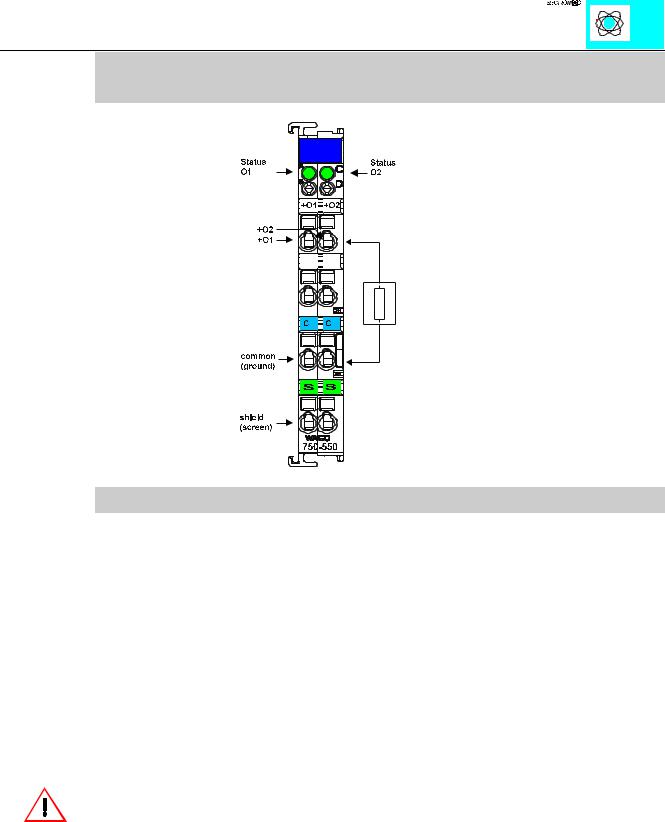
2 Channel Analog Outputs 0-10 V
PN 750-550, 750-580
Technical Description
This description is only intended for hardware version X X X X 2 A 0 1 - - - -. The serial number can be found on the right side of the module.
The output signal of 750-550/551 is a 0-10 V signal. Sensors may be connected to „O“ and to the common ground.
The shield is connected to „S“. The connection is made automatically when snapped onto the DIN rail.
These I/O modules are not provided with integrated power jumper contacts. The power supply is made by the data contacts with a DC-DC converter. The modules can work self-supporting.
Attention:
The lowest power jumper contact is not carried out for some modules (e.g. 4-channel)! A module which needs all contacts (e.g. 2 channel digital) may not be connected to the right hand side of modules which do not have 3 power jumper contacts (e.g. 4 channel modules).
The output module can be connected to all buscouplers of the :$*2Ç, 2Ç6<67(0 (except for the economy type)
Analog Outputs 750-550,580 |
1 |
:$*2Ç, 2Ç6<67(0