Материал: m013209e
Structure of input and output data:
The module is a combined analog input and output module with 2 x 16 bit input and output data. The transfer of the data to be transmitted and the received data is made via up to 3 output and 3 input bytes. One control byte and one status byte are used to control the floating data.
Requests are indicated by a change of a bit. An assigned bit indicates execution by adopting the value of the request bit.
Up to 3 characters which have been received via interface can be stored in the input bytes 0 to 2. The output bytes will contain the characters to be sent.
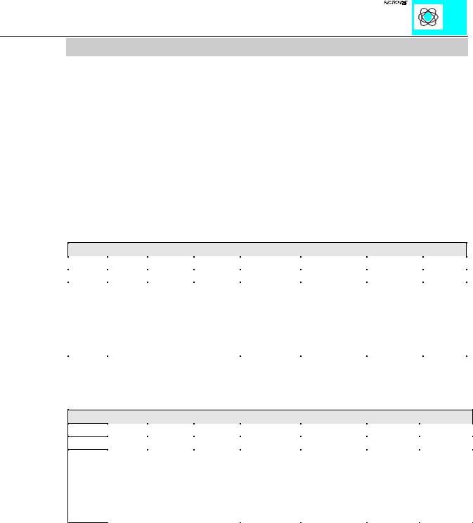
The control byte consists of the following bits:
Control Byte
Bit 7 |
Bit 6 |
Bit 5 |
Bit 4 |
Bit 3 |
Bit 2 |
Bit 1 |
Bit 0 |
0 |
OL2 |
OL1 |
OL0 |
0 |
IR |
RA |
TR |
Con- |
Frames available in output |
Constant |
Initialization |
Reception |
Trans- |
||
stant |
area, OL2 is always 0. |
value must |
request |
acknow- |
mission |
||
value |
eg. OL2, OL1, OL0 = 0,1,1 |
always be 0. |
|
ledgement |
request |
||
must |
3 characters should be sent |
|
|
|
|
||
always |
and put into the output. |
|
|
|
|
||
be 0. |
|
|
|
|
|
|
|
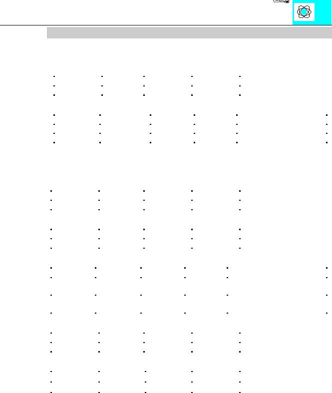
The status byte consists of the following bits:
Bit 7
0
Constant value must always be 0.
Status Byte
Bit 6 |
Bit 5 |
Bit 4 |
Bit 3 |
Bit 2 |
Bit 1 |
Bit 0 |
IL2 |
IL1 |
IL0 |
BUF_F |
IA |
RR |
TA |
Frames available in input |
Input buffer |
Initialization |
Reception |
Trans- |
||
area, IL2 is always 0. eg. |
is full. |
acknow- |
request |
mission |
||
IL2,IL1,IL0 = 0,1,0 |
|
|
ledgement |
|
acknow- |
|
2 characters were received |
|
|
|
ledgement |
||
and reside in input 0 and input |
|
|
|
|
||
1. |
|
|
|
|
|
|
RS232,TTY,RS485 750-650,651,653 |
6 |
:$*2Ç, 2Ç6<67(0

The PLC is able to control transmission and reception of data by means of the control byte and the status byte.
Initialization of the module:
·set IR in the control byte
·transmit/receive functions are blocked
·output/input buffers are erased
·serial interface module will load its configuration data
Transmitting data:
·TR¹TA: put characters into output byte 0 to 2
·amount of characters is specified in OL0 to OL2
·TR is inverted and read out
·characters are put into output buffer if TR=TA
Receiving data:
·RR¹RA: in input byte 0 to 2 characters are available
·amount of characters is specified in IL0 to IL2
·charactersin IL0 to IL2 are read out
·RA is inverted and read out
·all characters are read when RR=RA
The transmitting and receiving of data can be done simultaneously. The initialization request has prioirity and will stop transmitting and receiving of data immediately.
Message: input buffer full (Bit 3)
Input buffer is full. Data which are received now are lost.
RS232,TTY,RS485 750-650,651,653 |
7 |
:$*2Ç, 2Ç6<67(0
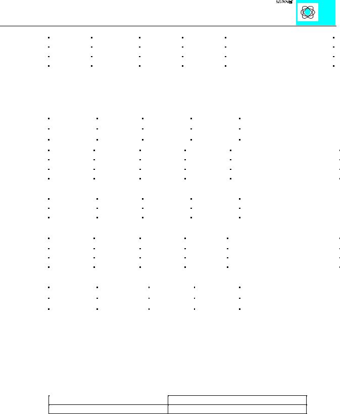
Examples:
The module is initialized.
- The initialization bit in the control byte is set.
Output byte 0 |
Control byte |
Output byte 2 |
Output byte 1 |
0x00 |
0000.0100 |
0x00 |
0x00 |
- After the initialization has been executed, the status byte will give back 000.0100.
Input byte 0 |
Status byte |
Input byte 2 |
Input byte 1 |
|
XX |
0XXX.X0XX |
XX |
XX |
Module is still being reset |
XX |
0XXX.X1XX |
XX |
XX |
Initialization completed |
Sending of the data string “Hello”:
- The first 3 characters and the buffer length of 3 are transmitted.
Output byte 0 |
|
Control byte |
‘H’ (0 x 48) |
|
0011.0000 |
Output byte 2 |
|
Output byte 1 |
|
‘l’ (0 x 6C) |
‘e’ (0 x 65) |
|
|
|
|
|
|
- The transmission request bit (TR) is inverted.
Output byte 0 |
|
Control byte |
‘H’ |
|
0011.0001 |
Output byte 2 |
|
Output byte 1 |
|
‘l’ |
‘e’ |
|
|
|
|
|
|
- As soon as TR=TA, the rest of the data can be sent.
Input byte 0 |
Status byte |
Input byte 2 |
Input byte 1 |
|
XX |
0XXX.XXX |
XX |
XX |
The data is still being transferred. |
|
0 |
|
|
|
XX |
0XXX.XXX |
XX |
XX |
Data transfer completed. |
|
1 |
|
|
|
- The last 2 characters and the buffer length of 2 are transmitted.
Output byte 0 |
|
Control byte |
‘l’ |
|
0010.0001 |
Output byte 2 |
Output byte 1 |
XX |
‘o’ (0 x 6F) |
- The transmission request bit (TR) is inverted.
Output byte 0 |
|
Control byte |
‘l’ |
|
0010.0000 |
Output byte 2 |
Output byte 1 |
XX |
‘o’ |
RS232,TTY,RS485 750-650,651,653 |
8 |
:$*2Ç, 2Ç6<67(0
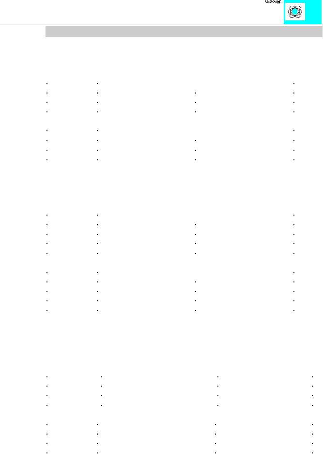
- As soon as TA = TR, the data has been transferred to the output buffer.
Input byte 0 |
Status byte |
Input byte 2 |
Input byte 1 |
|
XX |
0XXX.XXX1 |
XX |
XX |
The data is still being transferred. |
XX |
0XXX.XXX0 |
XX |
XX |
Data transfer completed. |
Receiving the character chain “WAGO”
- As soon as RA¹RR, the input bytes contain data.
|
Output byte 0 |
|
|
|
|
Control yte |
|
|
|
Output byte 2 |
|
|
Output byte 1 |
|
|
||||
|
XX |
|
|
|
|
0XXX.000X |
|
|
|
XX |
|
|
|
|
XX |
|
|
|
|
|
|
|
|
|
|
|
|
|
|
|
|
|
|||||||
|
Input byte 0 |
|
Status byte |
|
|
Input byte 2 |
|
Input byte 1 |
|
|
|
|
|||||||
|
XX |
|
0XXX.0X0X |
|
|
XX |
|
XX |
|
No received data available. |
|
||||||||
|
‘W’ (0 x 57) |
|
0011.0X1X |
|
‘G’ (0 x 47) |
‘A’ (0 x 41) |
|
The information is in the input bytes. |
|
||||||||||
|
|
|
|
|
|
|
|
|
|
|
|
|
|
|
|
|
|
|
|
- After the 3 characters have been processed, RA is inverted.
Output byte 0 |
Control byte |
Output byte 2 |
Output byte 1 |
XX |
0XXX.001X |
XX |
XX |
- If RA¹RR, the receiving of additional characters will continue.
Input byte 0 |
Status byte |
Input byte 2 |
Input byte 1 |
|
XX |
0XXX.0X1X |
XX |
XX |
No received data available. |
‘O’ (0 x 4F) |
0001.0X0X |
XX |
XX |
The information is in the input bytes. |
- After the characters have been processed, RA is inverted.
Output byte 0 |
Control byte |
Output byte |
Output byte |
XX |
0XXX.000X |
XX |
XX |
Notes:
0 x 23 is a hexadecimal value
0101.1001 is a binary value
An X indicates that this particular value has no importance. XX indicates that the whole value has no importance.
Status Indicators:
The 3 green LEDs have the following function:
Function
Output Status TxD
Non-Function
Input Status RxD
RS232,TTY,RS485 750-650,651,653 |
9 |
:$*2Ç, 2Ç6<67(0
Structure of the in and output data for Interbus
The module is a combined input and output module with 2 x 16 bit input and output data.
Outputs: |
|
|
Word |
Description |
|
D0 (bit 0-15) |
Output byte0 |
Control byte |
D1(bit16-31) |
Output byte2 |
Output byte1 |
Inputs: |
|
|
Word |
Description |
|
D0 (bit 0-15) |
Input byte0 |
Status byte |
D1(bit16-31) |
Input byte2 |
Input byte1 |
The RS232 module is also available with a data format of 5 bytes (item-no. 750- 650/000-001).
|
Outputs: |
|
|
|
|
Word |
Description |
|
|
|
D0 (bit 0-15) |
Control byte |
Output byte0 |
|
|
D1(bit16-31) |
Output byte1 |
Output byte2 |
|
|
D2(bit32-47) |
Output byte3 |
Output byte4 |
|
|
Inputs: |
|
|
|
|
Word |
Description |
|
|
|
D0 (bit 0-15) |
Status byte |
Input byte0 |
|
|
D1(bit16-31) |
Input byte1 |
Input byte2 |
|
|
D2(bit32-47) |
Input byte3 |
Input byte4 |
|
|
|
|
|
|
|
|
|
|
|
RS232,TTY,RS485 750-650,651,653 |
11 |
:$*2Ç, 2Ç6<67(0