Материал: m013205e
The numerical format
All analog values will be shown in a unit numerical format. The resolution is 12 Bits. The following table will explain the numerical format. (750-465, 466). The 3 LSBs are not taken into account.
Input current |
Input current |
Binary value |
|
|
|
|
|
0-20mA |
4-20mA |
|
|
Hex. |
Dec. |
Status |
LED |
>20,5 |
>20,5 |
0111 1111 1111 1111 |
7F FF |
32767 |
42 |
on |
|
|
|
|
|
|
|
|
|
20 |
20 |
0111 1111 1111 1111 |
7F FF |
32767 |
0 |
off |
|
|
|
|
|
|
|
|
|
10 |
12 |
0100 0000 |
0000 0XXX |
40 00 |
16384 |
0 |
off |
|
|
|
|
|
|
|
|
5 |
8 |
0010 0000 |
0000 0XXX |
20 00 |
8192 |
0 |
off |
|
|
|
|
|
|
|
|
2,5 |
6 |
0001 0000 |
0000 0XXX |
10 00 |
4096 |
0 |
off |
|
|
|
|
|
|
|
|
0,156 |
4,125 |
0000 0001 |
0000 0XXX |
01 00 |
256 |
0 |
off |
|
|
|
|
|
|
|
|
0,01 |
4,0078 |
0000 0000 |
0001 0XXX |
00 10 |
16 |
0 |
off |
|
|
|
|
|
|
|
|
0,005 |
4,0039 |
0000 0000 |
0000 1XXX |
00 08 |
8 |
0 |
off |
|
|
|
|
|
|
|
|
0 |
4 |
0000 0000 |
0000 0XXX |
00 00 |
7 |
0 |
off |
|
|
|
|
|
|
|
|
0 |
3,5 - 4 |
0000 0000 0000 0000 |
0 |
0 |
0 |
off |
|
|
|
|
|
|
|
|
|
0 |
0 - 3,5 |
0000 0000 0000 0000 |
0 |
0 |
41 |
on |
|
|
|
|
|
|
|
|
(4 -20 |
|
|
|
|
|
|
|
|
Analog Inputs 750-465,466,486 |
3 |
:$*2Ç, 2Ç6<67(0
The numerical format for Siemens
In addition to the full 16 bit indication of the measured value it is possible to use the ‘Siemens format’. The measured value is represented by the most significant 12 Bits. The 3 least significant Bits are reserved for diagnostic and status purposes. (750- 465/000-001).
Input |
Binary value |
X : without meaning |
|
|
|
|
current |
|
F : short circuit or |
Hex. |
Dec. |
Status |
LED |
0-20mA |
|
F : open circuit |
|
|
|
|
|
|
Ü : overflow |
|
|
|
|
|
|
X F Ü |
|
|
|
|
>20,5 |
0100 0000 0000 0 |
0 0 1 |
4001 |
16385 |
42 |
on |
|
|
|
|
|
|
|
20 |
0100 0000 0000 0 |
0 0 0 |
4000 |
16384 |
0 |
off |
|
|
|
|
|
|
|
10 |
0010 0000 0000 0 |
0 0 0 |
2000 |
8192 |
0 |
off |
|
|
|
|
|
|
|
5 |
0001 0000 0000 0 |
0 0 0 |
1000 |
4096 |
0 |
off |
|
|
|
|
|
|
|
2,5 |
0000 1000 0000 0 |
0 0 0 |
0800 |
2048 |
0 |
off |
|
|
|
|
|
|
|
1,25 |
0000 0100 0000 0 |
0 0 0 |
0400 |
1024 |
0 |
off |
|
|
|
|
|
|
|
0,625 |
0000 0010 0000 0 |
0 0 0 |
0200 |
512 |
0 |
off |
|
|
|
|
|
|
|
0,0976 |
0000 0000 0000 1 |
0 0 0 |
0008 |
8 |
0 |
off |
|
|
|
|
|
|
|
0 |
0000 0000 0000 0 |
0 0 0 |
0000 |
0 |
0 |
off |
|
|
|
|
|
|
|
Analog Inputs 750-465,466,486 |
4 |
:$*2Ç, 2Ç6<67(0
|
|
|
|
|
|
|
|
|
|
|
|
|
|
|
|
|
|
|
|
|
|
|
|
|
|
|
|
|
|
|
|
|
|
|
|
750-466/000-200 or 750-486: |
|
|
|
|
|
|
|
|
|
||
|
|
|
|
|
|
|
|
|
|
|
|
|
Input |
Binary value |
X : without meaning |
|
|
|
|
|
|
|
|
|
current |
|
F : short circuit or |
Hex. |
Dec. |
Status |
LED |
||||
|
4-20mA |
|
F : open circuit |
|
|
|
|
|
|
|
|
|
|
|
Ü : overflow |
|
|
|
|
|
|
|
|
|
|
|
X F Ü |
|
|
|
|
|
|
|
|
|
>20,5 |
0101 0000 0000 0 |
0 0 1 |
40 01 |
16385 |
42 |
|
on |
|||
|
|
|
|
|
|
|
|
|
|||
|
20 |
0101 0000 0000 0 |
0 0 0 |
50 00 |
20480 |
0 |
|
off |
|||
|
|
|
|
|
|
|
|
|
|||
|
16 |
0100 0000 0000 0 |
0 0 0 |
40 00 |
16384 |
0 |
|
off |
|||
|
|
|
|
|
|
|
|
|
|||
|
12 |
0011 0000 0000 0 |
0 0 0 |
30 00 |
12288 |
0 |
|
off |
|||
|
|
|
|
|
|
|
|
|
|||
|
8 |
0010 0000 0000 0 |
0 0 0 |
20 00 |
8192 |
0 |
|
off |
|||
|
|
|
|
|
|
|
|
|
|||
|
4,0078 |
0001 0000 0000 1 |
0 0 0 |
1008 |
4104 |
0 |
|
off |
|||
|
|
|
|
|
|
|
|
|
|||
|
4 |
0001 0000 0000 0 |
0 0 0 |
1000 |
4096 |
0 |
|
off |
|||
|
|
|
|
|
|
|
|
|
|||
|
<3,5 |
0001 0000 0000 0 |
0 1 1 |
1003 |
4099 |
0 |
|
on |
|||
|
|
|
|
|
|
|
|
|
|
|
|
If you have questions about the formatting of this data, please contact WAGO for I/O System technical support.
Analog Inputs 750-465,466,486 |
5 |
:$*2Ç, 2Ç6<67(0
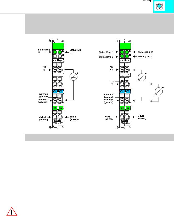
2 / 4 Channel Analog Inputs 0-10 V single ended
PN 750-467, 468, 487, 488
Technical Description
This description is only intended for hardware version X X X X 2 A 0 0 - - - -. The serial number can be found on the right side of the module.
The input channels are single ended and they have a common ground potential.
The inputs are connected to +I and M. The shield is connected to „S“. The connection is made automatically when snapped onto the DIN rail.
These I/O modules are not provided with integrated power jumper contacts. The power supply is made by the data contacts with a DC-DC converter. The modules can work self-supporting.
Attention:
The lowest power jumper contact is not carried out for some modules (e.g. 4-channel)! A module which needs all contacts (e.g. 2 channel digital) may not be connected to the right hand side of modules which do not have 3 power jumper contacts (e.g. 4 channel modules).
The input module can be connected to all buscouplers of the :$*2Ç, 2Ç6<67(0 (except for the economy type)
Analog Inputs 750-467,468,487,488 |
1 |
:$*2Ç, 2Ç6<67(0
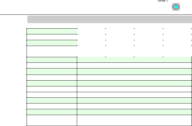
Technical Data:
Item Number 750-
Number of channels
Nominal voltage
Current consumption (internal)
Overvoltage protection
Signal voltage
Resistance
Resolution
Isolation
Conversion time
Bit width per channel
Operating temperature
Configuration
Wire connection
Dimensions (mm)WxHxL
|
|
|
|
|
|
|
|
|
|
|
|
|
|
|
|
|
|
|
|
|
|
|
|
|
|
|
|
|
|
|
|
|
|
|
|
467 |
|
468 |
487 |
|
|
|
488 |
|
2 |
|
4 |
2 |
|
|
|
4 |
|
|
via system voltage (DC DC converter) |
|
|
|||||
60 mA |
|
60 mA |
60 mA |
|
60 mA |
|||
|
|
|
|
|
|
|
|
|
35 V max.
0-10 V
133 kΩ typ.
12 Bit
500 V system/power supply
2 ms typ.
16 Bit Data, 8 Bit Control/Status
0°C....+55°C
none, optional via software parameter
CAGE CLAMP; 0.08 to 2.5mm2
12 x 64* x 100 (*from upper edge of the carrier rail)
Analog Inputs 750-467,468,487,488 |
2 |
:$*2Ç, 2Ç6<67(0