Материал: m013205e
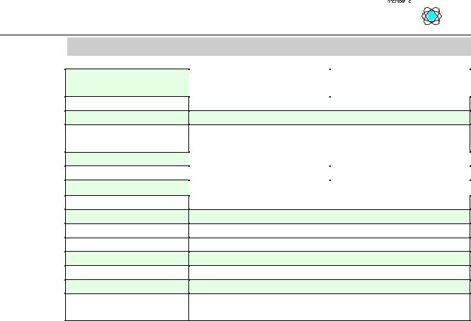
Technical Data:
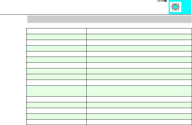
Item Number 750-
Number of inputs
Voltage supply
Sensor types
Cold junction compensation
Measuring accuracy
Resolution
Isolation DC/DC
Conversion time
Input current (internal)
Bit width per channel
Configuration
Operating temperature
Connection technique
Dimensions (mm)WxHxL
Presetting
462, 469
2 (differential input, max. +/- 3.5V)
via system voltage
J, K, B, E, N, R, S, T, U, L, mV Messung
on each module
<25 µV, typ. 15 µV
0.1°C per Bit
500V system / power supply
640 µs
65 mA max.
16 Bit: data; 8 Bit: control/status* (detection of broken wire 750-469)
none, optional via software parameter
0°C....+55°C
CAGE CLAMP; 0.08 to 2.5mm2
12 x 64* x 100 (*from upper edge of the carrier rail)
-100°C / +1370°C, Typ K
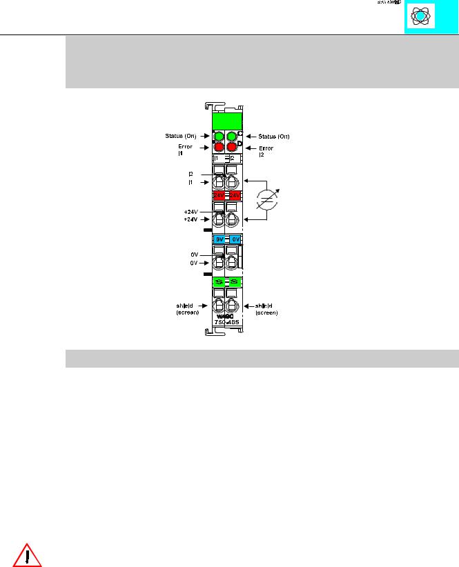
The function module 750-462 permits the direct connection of thermocouple sensors. The module is suitable for 2 or 3-wire thermocouples. For the 2-wire connection technique, connect the thermocouple wires between TCand TC+ . For the 3-conductor technique the shield is also connected. The operation of grounded sensors is provided by means of internal electrical isolation.
The function module 750-469 alos detects a broken wire. You can find the PNs for the different sensor types for 750-462 in the following table.
Warning: Both inputs are referenced to a common potential (not isolated)!
The linearization is provided over the complete range by a microprocessor. The temperature ranges of the sensors are represented with a resolution of 1 bit per 0.1°C in one word (16 Bit). Thus, 0°C corresponds to the value 0000, and 25.5°C correspond to the value 0 x 00FF. Temperatures below 0°C are represented in two’s complement with a leading ‘1’.
Within the whole range of all thermocouples, the function module works like a ‘μV meter’. The voltage resolution is represented with 16 bits. A processor converts the voltage value into a numerical value proportional to the measured temperature of the selected type of thermocouple.
In order to compensate the offset voltage at the clamping point, a cold junction thermocouple compensation calculation is carried out. The circuit contains a temperature measuring sensor at the ‘CAGE CLAMP’ connection and considers the temperature offset voltage when calculating the measured value.
Input for thermocouple modules 750-462,469 |
2 |
:$*2Ç, 2Ç6<67(0
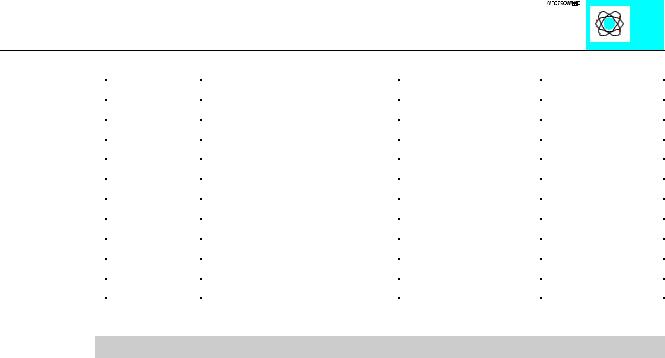
Temperature Ranges of the connectable sensors:
L |
-25°C....+900°C |
|
|
K |
-100°C...1370°C (Default) |
|
|
J |
-100°C...+1200°C |
750-462/000-006 |
750-469/000-006 |
E |
-100°C...1000°C |
750-462/000-008 |
750-469/000-008 |
T |
-100°C...+400°C |
750-462/000-002 |
750-469/000-002 |
N |
-100°C...+1300°C |
750-462/000-009 |
750-469/000-009 |
U |
-25°C...+600°C |
750-462/000-011 |
750-469/000-011 |
B |
600°C...+1800°C |
750-462/000-007 |
750-469/000-007 |
R |
0°C...+1700°C |
750-462/000-010 |
750-469/000-010 |
S |
0°C...+1700°C |
750-462/000-001 |
750-469/000-001 |
mV-Meter |
-120 mV...+120 mV |
750-462/000-003 |
750-469/000-003 |
Table 1: Temperature ranges of the connectable sensors
Attention: The range of the mV Meter is 0 to 120mV at the moment!
LED functions:
green LED: Function ON: Normal
OFF: Watchdog-Timer Overflow
If the PLC does not transmit processing data for 100 ms the green LED stops lightning.
red LED: Error
ON: Overor underrange or broken wire (bei 750-469) OFF: voltage is in the measuring range
Input for thermocouple modules 750-462,469 |
3 |
:$*2Ç, 2Ç6<67(0
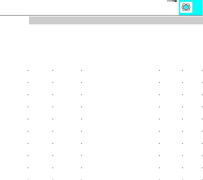
The numerical formats
All temperature values are represented in a uniform numerical format. In the default setting (type K) one Bit corresponds to 0.1°C. The output value corresponds to the temperature range of each sensor as defined according to standards. By using a configuration tool, the output formats can be chosen. The linearization can be switched off and the building of the reference temperature can be switched off also. The following table identifies the numerical format on the default range (type K).
Temp. |
Voltage |
Binary Value |
|
|
°C |
(uV) |
|
Hex. |
Dec. |
850 |
35314 |
0010 0001 0011 0100 |
2134 |
8500 |
|
|
|
|
|
100 |
4095 |
0000 0011 1110 1000 |
03E8 |
1000 |
|
|
|
|
|
25,5 |
1021 |
0000 0000 1111 1111 |
00FF |
255 |
|
|
|
|
|
0,1 |
4 |
0000 0000 0000 0001 |
0001 |
1 |
|
|
|
|
|
0 |
0 |
0000 0000 0000 0000 |
0000 |
0 |
|
|
|
|
|
-0,1 |
-4 |
1111 1111 1111 1111 |
FFFF |
-1 |
|
|
|
|
|
-25,5 |
-986 |
1111 1111 0000 0001 |
FF01 |
-255 |
|
|
|
|
|
-100 |
-3553 |
1111 1100 0001 1000 |
FC18 |
-1000 |
|
|
|
|
|
Table 2: Numerical formats
Input for thermocouple modules 750-462,469 |
4 |
:$*2Ç, 2Ç6<67(0
2 Channel Analog Input 0-20 mA / 4- 20 mA single ended
PN 750-465, 750-466, 750-486, 750-465/000-001
Technical Description
This description is only intended for hardware version X X X X 2 A 0 1 - - - -. The serial number can be found on the right side of the module.
The input channels are single ended and they have a common ground potential.
The inputs are connected to +I. Via 24 V / 0 V a sensor can be provided directly from the module. Power connections are made automatically from module to module when snapped onto the DIN rail.
The shield is connected to „S“. The connection is made automatically when snapped onto the DIN rail.
Attention:
The lowest power jumper contact is not carried out for some modules (e.g. 4-channel)! A module which needs all contacts (e.g. 2 channel digital) may not be connected to the right hand side of modules which do not have 3 power jumper contacts (e.g. 4 channel modules).
The input module can be connected to all buscouplers of the :$*2Ç, 2Ç6<67(0 (except for the economy type)
Analog Inputs 750-465,466,486 |
1 |
:$*2Ç, 2Ç6<67(0
Technical Data:
Item Number 750-
Number of channels
Nominal voltage
Current consumption (internal)
Overvoltage protection
Signal current
Resistance
Resolution
Isolation
Conversion time
Bit width per channel
Operating temperature
Configuration
Wire connection
Dimensions (mm)WxHxL
|
|
|
|
|
|
|
|
|
|
|
|
|
|
|
|
|
|
|
|
|
|
|
|
465 |
466 |
|
|
|
|
465/000-001 |
486 |
|
|
|
|
2
24 V DC (-15% / +20%) via power jumper contacts
75 mA typ.
|
35 V max. |
|
0-20mA |
|
4-20mA |
|
50 Ω |
typ. |
12 Bit
500 V system/power supply
2 ms typ.
16 Bit Data, 8 Bit Control/Status
0°C....+55°C
none, optional via software parameter
CAGE CLAMP; 0.08 to 2.5mm2
12 x 64* x 100 (*from upper edge of the carrier rail)
Analog Inputs 750-465,466,486 |
2 |
:$*2Ç, 2Ç6<67(0