Материал: m013205e
Technical Data:
Item Number 750-
Number of inputs
Input current (internal)
Voltage supply
Sensor types
Wire connection
Temperature range
Resolution
Isolation DC/DC
Measuring current
Conversion time
Bit width per channel
Configuration
Operating temperature
Wire connection
Dimensions (mm)WxHxL
Presetting
461, 481, 461/000-002, 461/000-003
2
65 mA
via system voltage
PT100, PT 200, PT 500, PT1000, Ni100, Ni120, Ni1000
2-conductor, 3-conductor (presetting)
PT: -200°C..+850°C Ni:-60°C...250°C
0.1°C over the whole area
400V system / power supply
0.5mA type
640 µs
16 bits: data; 8 bits: control/status
none, optional via software parameter
0°C....+55°C
CAGE CLAMP; 0.08 to 2.5mm2
12 x 64* x 100 (*from upper edge of the carrier rail)
3-conductor PT100
The function module 750-461 allows the direct connection of PTor Ni-resistance sensors. The module is suitable for 2- or 3-wire RTDs. Connection is made according to the above wiring diagram.
Linearization is accomplished over the entire measurement range by a microprocessor. The temperature ranges of the above listed RTD types is available to the user. The temperature ranges of the sensors are represented with a resolution of 1 bit per 0.1° C in one word (16 bits). Resulting from this, 0°C corresponds to the hexadecimal value 0000 and 100°C is 03E8 (dez.1000). Temperatures below 0° are represented in two’s complement with a leading ‘1’.
The function module works in the defined temperature range for the PT100 sensors of -200°C to +850°C. The voltage resolution is represented with 16 bits. An A/D converter and processor converts the voltage value to a numerical value proportional to the temperature of the selected resistance temperature sensor.
A short circuit or an interruption of the RTD wire is transmitted to the bus module and indicated by the red error LED. The green LED identifies that the module is communicating properly with the connected Buscoupler.
Input for PT100 750-461, 481 |
2 |
:$*2Ç, 2Ç6<67(0
The numerical format
All temperature values will be shown in a unit numerical format. If the mode ‘DEFAULT’ is selected each bit corresponds to 0.1°C. The possible numerical range refers to the standardized temperature range of the used sensors. The following table will explain the numerical format on a preset PT100. In the third column the numerical format for PT1000 (750-461/000-003) is explained.
Temperature |
Voltage |
Voltage |
Binary Value |
|
|
°C |
(Ohm) |
(Ohm) |
|
Hex. |
Dec. |
|
>400 |
|
|
|
|
|
|
|
|
|
|
850 |
390.481 |
1384,998 |
0010 0001 0011 0100 |
2134 |
8500 |
|
|
|
|
|
|
100 |
138.506 |
1099,299 |
0000 0011 1110 1000 |
03E8 |
1000 |
|
|
|
|
|
|
25.5 |
109.929 |
1000,391 |
0000 0000 1111 1111 |
00FF |
255 |
|
|
|
|
|
|
0.1 |
100.039 |
1000 |
0000 0000 0000 0001 |
0001 |
1 |
|
|
|
|
|
|
0 |
100 |
999,619 |
0000 0000 0000 0000 |
0000 |
0 |
|
|
|
|
|
|
-0.1 |
99.970 |
901,929 |
1111 1111 1111 1111 |
FFFF |
-1 |
|
|
|
|
|
|
-25.5 |
90.389 |
184,936 |
1111 1111 0000 0001 |
FF01 |
-255 |
|
|
|
|
|
|
-200 |
18.192 |
|
1111 1000 0011 0000 |
F830 |
-2000 |
|
|
|
|
|
|
|
<18 |
|
1000 0000 0000 0000 |
8000 |
-32767 |
|
|
|
|
|
|
Table 1 |
|
|
|
|
|
Input for PT100 750-461, 481 |
3 |
:$*2Ç, 2Ç6<67(0

The numerical format for 750-461/000-002
All temperature values will be shown in a unit numerical format. Each bit corresponds to 0.1°C. The following table will explain the numerical format for 750-461/000-002.
Voltage |
Binary value |
|
|
(Ohm) |
|
Hex. |
Dez. |
10 |
0000 0000 0110 0100 |
00 64 |
100 |
|
|
|
|
100 |
0000 0011 1110 1000 |
03 E8 |
1000 |
|
|
|
|
200 |
0000 0111 1101 0000 |
07 D0 |
2000 |
|
|
|
|
300 |
0000 1011 1011 1000 |
0B B8 |
3000 |
|
|
|
|
400 |
0000 1111 1010 0000 |
0F A0 |
4000 |
|
|
|
|
500 |
0001 0011 1000 1000 |
13 88 |
5000 |
|
|
|
|
1000 |
0010 0111 0001 0000 |
27 10 |
10000 |
|
|
|
|
1200 |
0010 1110 1110 0000 |
2E E0 |
12000 |
|
|
|
|
Input for PT100 750-461, 481 |
4 |
:$*2Ç, 2Ç6<67(0
The numerical format for Siemens
In addition to the full 16 bit indication of the measured value it is possible to use the ‘Siemens format’. The measured value is represented by the most significant 12 Bits. The 4 least significant Bits are reserved for diagnostic and status purposes. (750-481)
Temp. |
Ohm |
Binary value |
X : without meaning |
|
|
°C |
|
|
F : short circuit or |
Hex. |
Dec. |
|
|
|
F : open circuit |
|
|
|
|
|
Ü : overflow |
|
|
|
|
|
X F Ü |
|
|
|
>400 |
1111 1111 1111 1 |
0 0 1 |
FF F9 |
65529 |
|
|
|
|
|
|
883 |
400 |
0111 1111 1111 1 |
0 0 0 |
7F F8 |
32866 |
|
|
|
|
|
|
560 |
300 |
0110 0000 0000 0 |
0 0 0 |
60 00 |
24576 |
|
|
|
|
|
|
266 |
200 |
0100 0000 0000 0 |
0 0 0 |
40 00 |
16384 |
|
|
|
|
|
|
0 |
100 |
0010 0000 0000 0 |
0 0 0 |
20 00 |
8192 |
|
|
|
|
|
|
-125 |
50 |
0001 0000 0000 0 |
0 0 0 |
10 00 |
4096 |
|
|
|
|
|
|
-185 |
25 |
0000 0101 0000 0 |
0 0 0 |
500 |
1280 |
|
|
|
|
|
|
-200 |
20 |
0000 0100 0000 0 |
0 0 0 |
400 |
1024 |
|
|
|
|
|
|
<-200 |
0 |
0000 0000 0000 0 |
0 0 1 |
1 |
1 |
|
|
|
|
|
|
If you have questions about the formatting of this data, please contact WAGO for I/O System technical support.
Input for PT100 750-461, 481 |
5 |
:$*2Ç, 2Ç6<67(0
Input for Thermocouple Modules
PN 750-462, 750-469, 750-462/000-XXX
Technical description:
This description is only intended for hardware version X X X X 2 A 0 1 - - - -. The serial number can be found on the right side of the module.
The following description is preliminary and is applicable only to the factory configuration.
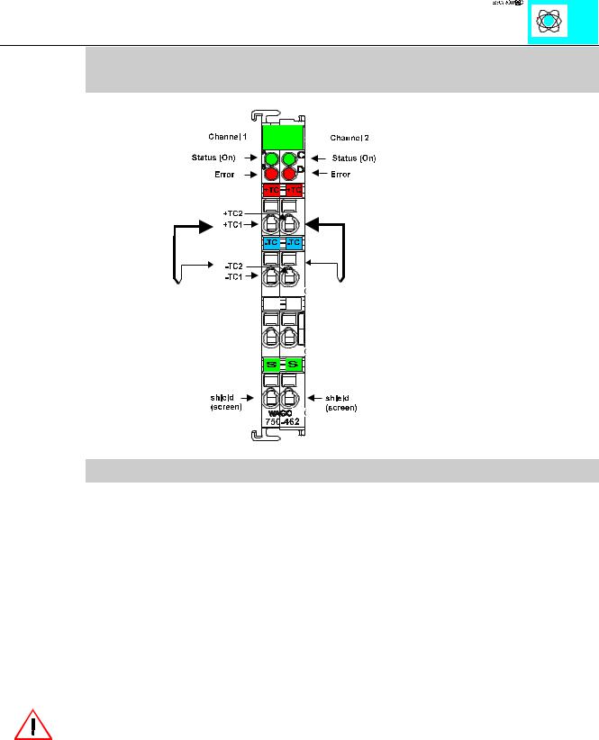
The shield is connected to „S“. The connection is made automatically when snapped onto the DIN rail.
These I/O modules are not provided with integrated power jumper contacts. The power supply is made by the data contacts with a DC-DC converter. The modules can work self-supporting.
Attention:
The lowest power jumper contact is not carried out for some modules (e.g. 4-channel)! A module which needs all contacts (e.g. 2 channel digital) may not be connected to the right hand side of modules which do not have 3 power jumper contacts (e.g. 4 channel modules).
The thermocouple module can be connected to all buscouplers of the :$*2Ç, 2Ç6<67(0 (except for the economy type)
Input for thermocouple modules 750-462,469 |
1 |
:$*2Ç, 2Ç6<67(0